Main Content

lidarPointCloudGenerator

Generate lidar point cloud data for driving scenario or RoadRunner Scenario

Since R2020a

Description

The lidarPointCloudGenerator System object™ generates detections from a lidar sensor mounted on an ego vehicle. All detections are referenced to the coordinate system of the ego vehicle or the vehicle-mounted sensor. You can use the lidarPointCloudGenerator object in a scenario containing actors and trajectories, which you can create by using a drivingScenario object. You can use the addSensors object function of the drivingScenario object to register the lidar as a sensor with the driving scenario. Then, you can call the lidar sensor object without any input arguments during the simulation. For more information, see Syntax Description For No Actor Pose Inputs.

You can also use the lidarPointCloudGenerator object with vehicle actors in RoadRunner Scenario simulation. First you must create a SensorSimulation object to interface sensors with RoadRunner Scenario and then register the lidar as a sensor model using the addSensors object function before simulation. You can then call the object without any input arguments during the RoadRunner Scenario simulation.

Using a statistical sensor model, lidarPointCloudGenerator object can simulate real detections with added random noise.

To generate lidar point clouds:

  1. Create the lidarPointCloudGenerator object and set its properties.

  2. Call the object with or without arguments, as if it were a function.

To learn more about how System objects work, see What Are System Objects?

Creation

Description

lidar = lidarPointCloudGenerator creates a lidarPointCloudGenerator object with default property values to generate a point cloud for a lidar sensor.

example

lidar = lidarPointCloudGenerator(Name,Value) sets properties using one or more name-value pairs. For example, lidarPointCloudGenerator('DetectionCoordinates','Sensor Cartesian','MaxRange',200) creates a lidar point cloud generator that reports detections in the sensor Cartesian coordinate system and has a maximum detection range of 200 meters. Enclose each property name in quotes.

Properties

expand all

Unless otherwise indicated, properties are nontunable, which means you cannot change their values after calling the object. Objects lock when you call them, and the release function unlocks them.

If a property is tunable, you can change its value at any time.

For more information on changing property values, see System Design in MATLAB Using System Objects.

Location of the lidar sensor center, specified as a [x y] vector. The SensorLocation and Height properties define the coordinates of the lidar sensor with respect to the ego vehicle coordinate system. The default value corresponds to a lidar sensor mounted on a sedan, at the center of the roof's front edge. Units are in meters.

Example: [4 0.1]

Data Types: double

Unique sensor identifier, specified as a positive integer. This property distinguishes detections that come from different sensors in a multisensor system.

Example: 5

Data Types: double

Required time interval between sensor updates, specified as a positive real scalar. The drivingScenario object calls the lidar point cloud generator at regular time intervals. lidarPointCloudGenerator object generates new detections at intervals defined by the UpdateInterval property. The value of the UpdateInterval property must be an integer multiple of the simulation time interval. Updates requested from the sensor between update intervals contain no detections. Units are in seconds.

Example: 5

Data Types: double

Sensor height above the vehicle ground plane, specified as a positive real scalar. The default value corresponds to a lidar sensor mounted on a sedan, at the center of the roof's front edge. Units are in meters.

Example: 1.5

Data Types: double

Yaw angle of the lidar sensor, specified as a real scalar. The yaw angle is the angle between the center line of the ego vehicle and the downrange axis of the lidar sensor. A positive yaw angle corresponds to a clockwise rotation when looking in the positive direction of the z-axis of the ego vehicle coordinate system. Units are in degrees.

Example: -4

Data Types: double

Pitch angle of the lidar sensor, specified as a real scalar. The pitch angle is the angle between the downrange axis of the lidar sensor and the x-y plane of the ego vehicle coordinate system. A positive pitch angle corresponds to a clockwise rotation when looking in the positive direction of the y-axis of the ego vehicle coordinate system. Units are in degrees.

Example: 3

Data Types: double

Roll angle of the lidar sensor, specified as a real scalar. The roll angle is the angle of rotation of the downrange axis of the lidar sensor around the x-axis of the ego vehicle coordinate system. A positive roll angle corresponds to a clockwise rotation when looking in the positive direction of the x-axis of the coordinate system. Units are in degrees.

Example: -4

Data Types: double

Maximum detection range, specified as a positive real scalar. The sensor cannot detect roads and actors beyond this range. Units are in meters.

Example: 200

Data Types: double

Accuracy of range measurements, specified as a positive real scalar. Units are in meters.

Example: 0.01

Data Types: single | double

Azimuth resolution of the lidar, specified as a positive real scalar. The azimuth resolution defines the minimum separation in azimuth angle at which the lidar can distinguish two targets. Units are in degrees.

Example: 0.5

Data Types: single | double

Elevation resolution of the lidar, specified as a positive real scalar. The elevation resolution defines the minimum separation in elevation angle at which the lidar can distinguish two targets. Units are in degrees.

Example: 0.5

Data Types: single | double

Azimuth limits of lidar, specified as a 1-by-2 real-valued vector of the form [min, max]. Units are in degrees.

Example: [-100 50]

Data Types: single | double

Elevation limits of lidar, specified as a 1-by-2 real-valued vector of the form [min, max]. Units are in degrees.

Example: [-10 10]

Data Types: single | double

Enable adding noise to lidar sensor measurements, specified as true or false. Set this property to true to add noise to the sensor measurements. Otherwise, the measurements have no noise.

Data Types: logical

Output the generated data as an organized point cloud, specified as true or false. Set this property to true to output an organized point cloud. Otherwise, the output is unorganized.

Data Types: logical

Include ego vehicle in the generated point cloud, specified as true or false. Set this property to true to include the ego vehicle in the output. Otherwise, the output point cloud has no ego vehicle.

Data Types: logical

Include road mesh data in the generated point cloud, specified as true or false. Set this property to true to generate point cloud data from the input road mesh, rdMesh. Otherwise, the output point cloud has no road mesh data and you cannot specify rdMesh.

The HasRoadsInputPort property is always true if you register the sensor with the scenario using the addSensors function.

Data Types: logical

ActorID of ego vehicle, specified as a positive integer scalar. ActorID is the unique identifier for an actor.

Example: 4

Data Types: single | double

Coordinate system of reported detections, specified as one of these values:

  • 'Ego Cartesian' — Detections are reported in the ego vehicle Cartesian coordinate system.

  • 'Sensor Cartesian' — Detections are reported in the sensor Cartesian coordinate system.

Data Types: char | string

Actor profiles, specified as a structure or as an array of structures. Each structure contains the physical and radar characteristics of an actor.

  • If ActorProfiles is a single structure, all actors passed into the lidarPointCloudGenerator object use this profile.

  • If ActorProfiles is an array, each actor passed into the object must have a unique actor profile.

To generate an array of structures for your driving scenario, use the actorProfiles function. The table shows the valid structure fields. If you do not specify a field, the fields are set to their default values. If no actors are passed into the object, then the ActorID field is not included.

FieldDescription
ActorIDScenario-defined actor identifier, specified as a positive integer.
ClassIDClassification identifier, specified as a nonnegative integer. 0 represents an object of an unknown or unassigned class.
LengthLength of actor, specified as a positive real-valued scalar. Units are in meters.
WidthWidth of actor, specified as a positive real-valued scalar. Units are in meters.
HeightHeight of actor, specified as a positive real-valued scalar. Units are in meters.
OriginOffsetOffset of actor's rotational center from its geometric center, specified as a real-valued vector of the form [x, y, z]. The rotational center, or origin, is located at the bottom center of the actor. For vehicles, the rotational center is the point on the ground beneath the center of the rear axle. Units are in meters.
MeshVerticesMesh vertices of actor, specified as an n-by-3 real-valued matrix of vertices. Each row in the matrix defines a point in 3-D space.
MeshFacesMesh faces of actor, specified as an m-by-3 matrix of integers. Each row of MeshFaces represents a triangle defined by the vertex IDs, which are the row numbers of vertices.
RCSPatternRadar cross-section (RCS) pattern of actor, specified as a numel(RCSElevationAngles)-by-numel(RCSAzimuthAngles) real-valued matrix. Units are in decibels per square meter.
RCSAzimuthAnglesAzimuth angles corresponding to rows of RCSPattern, specified as a vector of values in the range [–180, 180]. Units are in degrees.
RCSElevationAnglesElevation angles corresponding to rows of RCSPattern, specified as a vector of values in the range [–90, 90]. Units are in degrees.

For full definitions of the structure fields, see the actor and vehicle functions.

Usage

Description

No Actor Pose Inputs

[ptCloud,isValidTime] = lidar() generates a lidar point cloud, ptCloud and returns isValidTime, which indicates whether the point cloud is generated at the current simulation time without any input arguments. Use this syntax after you add the sensors to the driving scenario using the addSensors function. This syntax provides significant performance improvements over syntaxes with input arguments. For more information on performance improvements, see Improved Simulation Performance Using New Syntax Without Actor Pose Inputs.

[ptCloud,isValidTime,clusters] = lidar() additionally returns clusters, which contains the classification data of the generated point cloud.

Manually Input Actor Poses

ptCloud = lidar(actors,rdMesh,simTime) creates a statistical sensor model to generate a lidar point cloud, ptCloud, from sensor measurements taken of actors, actors, at the current simulation time, simTime. An extendedObjectMesh object, rdMesh, contains road data around the ego vehicle.

example

[ptCloud,isValidTime] = lidar(actors,rdMesh,simTime) additionally returns isValidTime, which indicates whether the point cloud is generated at the specified simulation time.

[ptCloud,isValidTime,clusters] = lidar(actors,rdMesh,simTime) additionally returns clusters, which contains the classification data of the generated point cloud.

[___] = lidar(actors,simTime) excludes road mesh data from the generated point cloud by disabling specification of the rdMesh input. Using this syntax, you can return any of the outputs described in the previous syntaxes.

To exclude road mesh data, set the HasRoadsInputPort property to false.

Input Arguments

expand all

Scenario actor poses, specified as a structure or structure array. Each structure corresponds to an actor. You can generate this structure using the actorPoses function. You can also create these structures manually. The table shows the properties that the object uses to generate detections. All other actor properties are ignored.

FieldDescription
ActorID

Scenario-defined actor identifier, specified as a positive integer.

Position

Position of actor, specified as a real-valued vector of the form [x y z]. Units are in meters.

Velocity

Velocity (v) of actor in the x- y-, and z-directions, specified as a real-valued vector of the form [vx vy vz]. Units are in meters per second.

Roll

Roll angle of actor, specified as a real-valued scalar. Units are in degrees.

Pitch

Pitch angle of actor, specified as a real-valued scalar. Units are in degrees.

Yaw

Yaw angle of actor, specified as a real-valued scalar. Units are in degrees.

AngularVelocity

Angular velocity (ω) of actor in the x-, y-, and z-directions, specified as a real-valued vector of the form [ωx ωy ωz]. Units are in degrees per second.

For full definitions of the structure fields, see the actor and vehicle functions.

Data Types: struct

Mesh representation of roads near to the actor, specified as an extendedObjectMesh object.

Current simulation time, specified as a positive real scalar. The drivingScenario object calls the lidar point cloud generator at regular time intervals to generate new point clouds at intervals defined by the UpdateInterval property. The value of the UpdateInterval property must be an integer multiple of the simulation time interval. Updates requested from the sensor between update intervals do not generate a point cloud. Units are in seconds.

Example: 10.5

Data Types: double

Output Arguments

expand all

Point cloud data, returned as a pointCloud object.

Valid time to generate point cloud, returned as 0 or 1. isValidTime is 0 when updates are requested at times that are between update intervals specified by UpdateInterval.

Data Types: logical

Classification data of the generated point cloud, returned as an N-by-2 vector. The vector defines the IDs of the target from which the point cloud was generated. N is equal to the Count property of the pointCloud object. The vector contains ActorID in the first column and ClassID in the second column.

Object Functions

To use an object function, specify the System object as the first input argument. For example, to release system resources of a System object named obj, use this syntax:

release(obj)

expand all

isLockedDetermine if System object is in use
stepRun System object algorithm
releaseRelease resources and allow changes to System object property values and input characteristics
resetReset internal states of System object

Examples

collapse all

Generate lidar point cloud data for a driving scenario with multiple actors by using the lidarPointCloudGenerator System object. Create the driving scenario by using drivingScenario object. It contains an ego-vehicle, pedestrian and two other vehicles.

Create and plot a driving scenario with multiple vehicles

Create a driving scenario.

scenario = drivingScenario;

Add a straight road to the driving scenario. The road has one lane in each direction.

roadCenters = [0 0 0; 70 0 0];
laneSpecification = lanespec([1 1]);
road(scenario,roadCenters,'Lanes',laneSpecification);

Add an ego vehicle to the driving scenario.

egoVehicle = vehicle(scenario,'ClassID',1,'Mesh',driving.scenario.carMesh);
waypoints = [1 -2 0; 35 -2 0];
smoothTrajectory(egoVehicle,waypoints,10);

Add a truck, pedestrian, and bicycle to the driving scenario and plot the scenario.

truck = vehicle(scenario,'ClassID',2,'Length', 8.2,'Width',2.5,'Height',3.5, ...
    'Mesh',driving.scenario.truckMesh);
waypoints = [70 1.7 0; 20 1.9 0];
smoothTrajectory(truck,waypoints,15);

pedestrian = actor(scenario,'ClassID',4,'Length',0.24,'Width',0.45,'Height',1.7, ...
    'Mesh',driving.scenario.pedestrianMesh);
waypoints = [23 -4 0; 10.4 -4 0];
smoothTrajectory(pedestrian,waypoints,1.5);

bicycle = actor(scenario,'ClassID',3,'Length',1.7,'Width',0.45,'Height',1.7, ...
    'Mesh',driving.scenario.bicycleMesh);
waypoints = [12.7 -3.3 0; 49.3 -3.3 0];
smoothTrajectory(bicycle,waypoints,5);

plot(scenario,'Meshes','on')

Generate and plot lidar point cloud data

Create a lidarPointCloudGenerator System object.

lidar = lidarPointCloudGenerator;

Add actor profiles and the ego vehicle actor ID from the driving scenario to the System object.

lidar.ActorProfiles = actorProfiles(scenario);
lidar.EgoVehicleActorID = egoVehicle.ActorID;

Plot the point cloud data.

bep = birdsEyePlot('Xlimits',[0 70],'YLimits',[-30 30]);
plotter = pointCloudPlotter(bep);
legend('off');
while advance(scenario)
    tgts = targetPoses(egoVehicle);
    rdmesh = roadMesh(egoVehicle);
    [ptCloud,isValidTime] = lidar(tgts,rdmesh,scenario.SimulationTime);
    if isValidTime
        plotPointCloud(plotter,ptCloud);
    end
end

Figure contains an axes object. The axes object with xlabel X (m), ylabel Y (m) contains 7 objects of type patch, line.

Figure contains an axes object. The axes object with xlabel X (m), ylabel Y (m) is empty.

In this example, you will add sensors to a driving scenario using the addSensors function. Then, you obtain sensor measurments without providing any ground-truth actor pose inputs and visualize them.

Set Up Driving Scenario and Bird's-Eye-Plot

Create a driving scenario with an ego vehicle and two target vehicles. One target vehicle is in the front and the other is to the left of the ego-vehicle.

[scenario, egovehicle] = helperCreateDrivingScenario;

Configure a lidar sensor to be mounted at the center of the roof's front edge of the ego vehicle.

lidarSensor = lidarPointCloudGenerator(SensorIndex=1,SensorLocation=[1.5 0],ActorProfiles=actorProfiles(scenario));

Create a bird's-eye-plot to visualize the driving scenario.

[pcPlotter, lmPlotter, olPlotter, bepAxes] = helperCreateBEP;

Figure BEP contains an axes object. The axes object with xlabel X (m), ylabel Y (m) contains 3 objects of type line, patch. One or more of the lines displays its values using only markers These objects represent Lidar Point Cloud, Lane markings.

Add Sensors and Simulate Driving Scenario

Add the lidar sensor to the driving scenario using the addSensors function. You can add sensors to any vehicle in the driving scenario using the addSensors function by specifying the actor ID of the desired vehicle. For this example, specify the ego-vehicle actor ID.

addSensors(scenario,lidarSensor,egovehicle.ActorID);

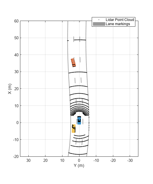
Simulate the driving scenario. Note that you are not providing any ground-truth actor pose inputs when you call lidarSensor object. The sensor automatically returns the point cloud based on the sensor parameters and actors within the sensor range.

legend(bepAxes,'show')
lookaheadDistance = 0:0.5:60;

while advance(scenario)
    
    lb = laneBoundaries(egovehicle,'XDistance',lookaheadDistance,'LocationType','inner');
    [lmv,lmf] = laneMarkingVertices(egovehicle);

    % Obtain lidar point cloud without any actor pose inputs
    [ptCloud,isValidTime] = lidarSensor();

    if isValidTime
        % Plot point cloud, vehicle outlines and lane markings
        plotPointCloud(pcPlotter,ptCloud);
        
        [objposition,objyaw,objlength,objwidth,objoriginOffset,color] = targetOutlines(egovehicle);
        plotOutline(olPlotter,objposition,objyaw,objlength,objwidth, ...
            OriginOffset=objoriginOffset,Color=color)

        plotLaneMarking(lmPlotter,lmv,lmf)
    end
end

Figure BEP contains an axes object. The axes object with xlabel X (m), ylabel Y (m) contains 3 objects of type line, patch. One or more of the lines displays its values using only markers These objects represent Lidar Point Cloud, Lane markings.

Helper Functions

helperCreateDrivingScenario creates a driving scenario by specifying the road and vehicle properties.

function [scenario, egovehicle] = helperCreateDrivingScenario
scenario = drivingScenario;
roadCenters = [-120 30 0;-60 0 0;0 0 0; 60 0 0; 120 30 0; 180 60 0];
lspc = lanespec(3);
road(scenario,roadCenters,Lanes=lspc);

% Create an ego vehicle that travels in the center lane at a velocity of 30 m/s.
egovehicle = vehicle(scenario,ClassID=1,Mesh=driving.scenario.carMesh);
egopath = [1.5 0 0; 60 0 0; 111 25 0];
egospeed = 30;
smoothTrajectory(egovehicle,egopath,egospeed);

% Add a target vehicle that travels ahead of the ego vehicle at 30.5 m/s in the right lane, and changes lanes close to the ego vehicle.    
ftargetcar = vehicle(scenario,ClassID=1,Mesh=driving.scenario.carMesh);
ftargetpath = [8 2; 60 -3.2; 120 33];
ftargetspeed = 40;
smoothTrajectory(ftargetcar,ftargetpath,ftargetspeed);

% Add a second target vehicle that travels in the left lane at 32m/s.    
ltargetcar = vehicle(scenario,ClassID=1,Mesh=driving.scenario.truckMesh);
ltargetpath = [-5.0 3.5 0; 60 3.5 0; 111 28.5 0];
ltargetspeed = 30;
smoothTrajectory(ltargetcar,ltargetpath,ltargetspeed);
end

helperCreateBEP creates a bird's-eye-plot for visualing the driving scenario simulation.

function [pcPlotter, lmPlotter, olPlotter,bepAxes] = helperCreateBEP()
figureName = "BEP";
Figure = findobj('Type','Figure',Name=figureName);
if isempty(Figure)
    screenSize = double(get(groot,'ScreenSize'));
    Figure = figure(Name=figureName);
    Figure.Position = [screenSize(3)*0.17 screenSize(4)*0.15 screenSize(3)*0.4 screenSize(4)*0.6];
    Figure.NumberTitle = 'off';
    Figure.MenuBar = 'none';
    Figure.ToolBar = 'none';
end
clf(Figure);
bepAxes = axes(Figure);
grid(bepAxes,'on');
legend(bepAxes,'hide');

bep = birdsEyePlot(Parent=bepAxes,XLim=[-20 60],YLim=[-35 35]);
pcPlotter = pointCloudPlotter(bep,DisplayName='Lidar Point Cloud');
lmPlotter = laneMarkingPlotter(bep,DisplayName="Lane markings");
olPlotter = outlinePlotter(bep);

end

Version History

Introduced in R2020a

expand all