Coordinate Systems in Automated Driving Toolbox
Automated Driving Toolbox™ uses these coordinate systems:
World: A fixed universal coordinate system in which all vehicles and their sensors are placed.
Vehicle: Anchored to the ego vehicle. Typically, the vehicle coordinate system is placed on the ground right below the midpoint of the rear axle.
Sensor: Specific to a particular sensor, such as a camera or a radar.
Spatial: Specific to an image captured by a camera. Locations in spatial coordinates are expressed in units of pixels.
Pattern: A checkerboard pattern coordinate system, typically used to calibrate camera sensors.
These coordinate systems apply across Automated Driving Toolbox functionality, from perception to control to driving scenario simulation. For information on specific differences and implementation details in the 3D simulation environment using the Unreal Engine® from Epic Games®, see Coordinate Systems for Unreal Engine Simulation in Automated Driving Toolbox.
World Coordinate System
All vehicles, sensors, and their related coordinate systems are placed in the world coordinate system. A world coordinate system is important in global path planning, localization, mapping, and driving scenario simulation. Automated Driving Toolbox uses the right-handed Cartesian world coordinate system defined in ISO 8855, where the Z-axis points up from the ground. Units are in meters.
Vehicle Coordinate System
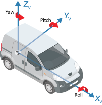
The vehicle coordinate system (XV, YV, ZV) used by Automated Driving Toolbox is anchored to the ego vehicle. The term ego vehicle refers to the vehicle that contains the sensors that perceive the environment around the vehicle.
The XV axis points forward from the vehicle.
The YV axis points to the left, as viewed when facing forward.
The ZV axis points up from the ground to maintain the right-handed coordinate system.
The vehicle coordinate system follows the ISO 8855 convention for rotation. Each axis is positive in the clockwise direction, when looking in the positive direction of that axis.
The origin of the vehicle coordinate system is located at these locations for different simulation environments and workflows.
| Simulation Environments and Workflows | Vehicle Coordinate System Origin |
|---|---|
| Cuboid Driving Scenario Simulation | On the ground, below the midpoint of the rear axle. |
| 3D Driving Scenario Simulation Using Unreal Engine | On the ground, below the longitudinal and lateral center of the vehicle. For more details, see Coordinate Systems for Unreal Engine Simulation in Automated Driving Toolbox. |
Visual perception Using a monoCamera
Object | On the ground, directly below the camera center (default). You
can change this to a different origin by specifying the
SensorLocation property of the monoCamera
object. |
Locations in the vehicle coordinate system are expressed in world units, typically meters.
Values returned by individual sensors are transformed into the vehicle coordinate system so that they can be placed in a unified frame of reference.
For global path planning, localization, mapping, and driving scenario simulation, the state of the vehicle can be described using the pose of the vehicle. The steering angle of the vehicle is positive in the counterclockwise direction.

Sensor Coordinate System
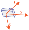
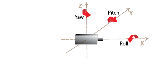
An automated driving system can contain sensors located anywhere on or in the vehicle. The location of each sensor contains an origin of its coordinate system. A camera is one type of sensor used often in an automated driving system. Points represented in a camera coordinate system are described with the origin located at the optical center of the camera.
The yaw, pitch, and roll angles of sensors follow an ISO convention. These angles have positive clockwise directions when looking in the positive direction of the Z-, Y-, and X-axes, respectively. These angles describe the orientation of the respective axes with the corresponding axes of the vehicle coordinate system.

Spatial Coordinate System
Spatial coordinates enable you to specify a location in an image with greater
granularity than pixel coordinates. In the pixel coordinate system, a pixel is treated
as a discrete unit, uniquely identified by an integer row and column pair, such as
(3,4). In the spatial coordinate system, locations in an image
are represented in terms of partial pixels, such as (3.3,4.7).
For more information on the spatial coordinate system, see Spatial Coordinates.
Pattern Coordinate System
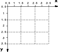
To estimate the parameters of a monocular camera sensor, a common technique is to calibrate the camera using multiple images of a calibration pattern, such as a checkerboard. In the pattern coordinate system, (XP, YP), the XP-axis points to the right and the YP-axis points down. The checkerboard origin is the bottom-right corner of the top-left square of the checkerboard.

Each checkerboard corner represents another point in the coordinate system. For example, the corner to the right of the origin is (1,0) and the corner below the origin is (0,1). For more information on calibrating a camera by using a checkerboard pattern, see Calibrate a Monocular Camera.