Extract Lane Information from Recorded Camera Data for Scene Generation
This example shows how to extract the lane information required for generating high-definition scenes from raw camera data.
Lane boundaries are crucial for interpreting the position and motion of moving vehicles. They are also useful for localizing vehicles on map.
In this example, you:
Detect lane boundaries in real-world vehicle coordinates from recorded forward-facing monocular camera images by using the
laneBoundaryDetectorobject.Track noisy lane boundaries by using the
laneBoundaryTrackerobject.
You can also use the Ground Truth Labeler app to resolve issues in detected lane boundaries. Then, you can use accurate lane boundary detections to generate high-definition road scene. For more information, see Generate RoadRunner Scene Using Processed Camera Data and GPS Data example.
Load Camera Sensor Data
This example requires the Scenario Builder for Automated Driving Toolbox™ support package. Check if the support package is installed and, if it is not installed, install it using the Get and Manage Add-Ons.
checkIfScenarioBuilderIsInstalled
Download a ZIP file containing the camera sensor data with camera parameters, and then unzip the file. This data set has been collected using a forward-facing camera mounted on an ego vehicle.
dataFolder = tempdir;
dataFilename = "PolysyncSensorData_23a.zip";
url = "https://ssd.mathworks.com/supportfiles/driving/data/"+dataFilename;
filePath = fullfile(dataFolder, dataFilename);
if ~isfile(filePath)
    websave(filePath,url);
end
unzip(filePath, dataFolder);
dataset = fullfile(dataFolder,"PolysyncSensorData");
data = load(fullfile(dataset,"sensorData.mat"));
monocamData = data.CameraData;
monocamData data is a table with two columns:
timeStamp— Time, in microseconds, at which the image data was captured.fileName— Filenames of the images in the data set.
The images are located in the Camera folder in the dataset directory. To load these images for detection and tracking, create an ImageDatastore object by using the imageDatastore function.
imageFolderName = "Camera";
imageFolderPath = fullfile(dataset,imageFolderName);
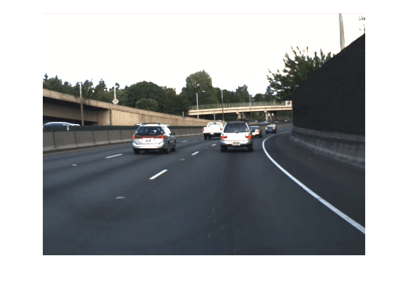
imds = imageDatastore(imageFolderPath);Preview the first image.
imshow(preview(imds));
Detect Lane Boundaries
Create a laneBoundaryDetector object to detect lane boundaries from camera images. The laneBoundaryDetector object requires the Deep Learning Toolbox™ Converter for ONNX™ Model Format support package. You can install Deep Learning Toolbox™ Converter for ONNX™ Model Format from the Add-On Explorer. For more information about installing add-ons, see Get and Manage Add-Ons
detector = laneBoundaryDetector;
Read an image from the datastore imds.
imgIdx = 5;
I = readimage(imds,imgIdx);
Detect lane boundary points in image coordinate by using the detect method of the laneBoundaryDetector object. Specify different parameters of the lane detector to get optimal performance. Overlay the lane boundary points on the image, and display the overlaid image using the helperViewLaneOnImage function.
Note: The lane boundary detector detects only the lane boundary points. It does not classify the lane boundary points into classes such as solid and dashed.
laneBoundaryPoints = detect(detector,I,ROI=240,DetectionThreshold=0.3,OverlapThreshold=0.1);
helperViewLaneOnImage(laneBoundaryPoints{1},I);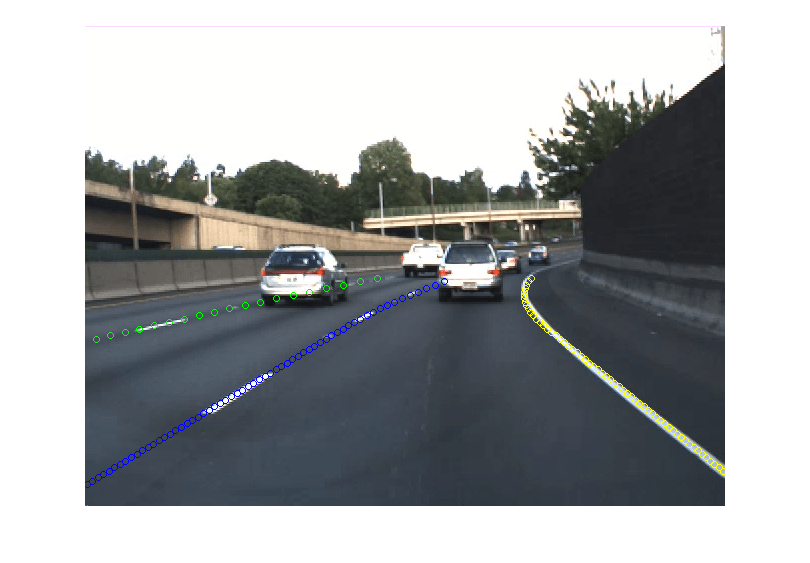
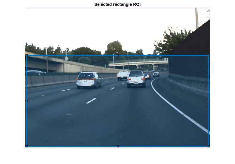
This example uses the ROI input argument of the detect method to crop the image, which specifies a region for lane detection. You can use ROI to enhance accuracy of lane detection in these scenarios:
Excluding Car Dashboard: For images captured from a dashboard camera, you can use the ROI to exclude the car dashboard, which can increase lane detection accuracy.
Eliminating Noisy Detection: For images with additional areas on the sides (such as sidewalks and buildings) can introduce noise in lane detection. The ROI parameter allows cropping out these areas, resulting in cleaner and more accurate lane detection.
Note: Choose the ROI in a manner that ensures the lane markings are visible within the cropped area.
To define a rectangular ROI interactively using the drawrectangle function, set the useInteractiveROI to true. After you draw the desired rectangle, close the figure to finalize the ROI selection.
useInteractiveROI = false;
f = figure;
ax = axes(f);
img = imds.preview();
imshow(img,Parent=ax)
if useInteractiveROI
    text(50,50,"Close the figure after drawing and placing the rectangle", ...
        FontSize=13,Color="r");
    rect = drawrectangle(ax);
    roi = ceil(rect.Position);
    waitfor(f);
else
    title("Selected rectangle ROI");
    position = [7 164 628 313];
    rect = drawrectangle(ax,Position=position);
    roi = ceil(rect.Position);
end
Read the first image. Crop the image by using the imcrop function.
imgStart = readimage(imds,1);
imgStart = imcrop(imgStart,roi);
imshow(imgStart);

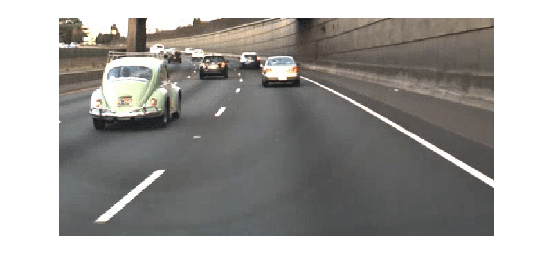
Read the last image, crop, and display the cropped image.
imgEnd = readimage(imds,numel(imds.Files));
imgEnd = imcrop(imgEnd,roi);
imshow(imgEnd);
Detect lane boundaries and detection scores for each image of the sequence by using the detect method.
[laneBoundaryPoints,scores] = detect(detector,imds,ROI=roi,DetectionThreshold=0.3,OverlapThreshold=0.1,MiniBatchSize=8);
The detect method detect lanes in the pixel coordinate system, which you must convert to the Coordinate Systems in Automated Driving Toolbox to use to generate a real world scene.
Convert lane detections from pixel coordinates to Coordinate Systems in Automated Driving Toolbox using these steps.
1. Specify the camera intrinsics. If you do not know the camera parameters, you can estimate them. For more information about estimating camera parameters, see Calibrate a Monocular Camera. You can also use the estimateMonoCameraFromScene function to estimate approximate camera parameters directly from a camera image.
Specify the camera intrinsic parameters of focal length (fx, fy), principal point (cx, cy), and image size.
intrinsics = data.Intrinsics
intrinsics = struct with fields:
           fx: 800
           fy: 800
           cx: 320
           cy: 240
    imageSize: [480 640]
2. Create a cameraIntrinsics object.
focalLength = [intrinsics.fx intrinsics.fy];
principalPoint = [intrinsics.cx intrinsics.cy];
imageSize = intrinsics.imageSize;
intrinsics = cameraIntrinsics(focalLength,principalPoint,imageSize);
3. Create a monoCamera object using the camera intrinsic parameters, height, and location. Display the object properties.
camHeight = data.cameraHeight;
camLocation = data.cameraLocation;
cameraParams = monoCamera(intrinsics,camHeight,SensorLocation=camLocation)
cameraParams =
  monoCamera with properties:

        Intrinsics: [1×1 cameraIntrinsics]
        WorldUnits: 'meters'
            Height: 1.1000
             Pitch: 0
               Yaw: 0
              Roll: 0
    SensorLocation: [2.1000 0]
4. Get lane detections in Coordinate Systems in Automated Driving Toolbox by using the imageToVehicle function.
laneBoundaryPointsVehicle = cell(numel(laneBoundaryPoints),1);
for i=1:numel(laneBoundaryPoints)
    laneBoundaryPointsVehicle{i,1} = cellfun(@(x) imageToVehicle(cameraParams,x), ...
        laneBoundaryPoints{i},UniformOutput=false);
end
Fit the parabolicLaneBoundary using the findParabolicLaneBoundaries function to the obtained lane detections in the Coordinate Systems in Automated Driving Toolbox.
numFrames = numel(laneBoundaryPointsVehicle);
laneBoundaries = cell(numFrames,1);
for i=1:numFrames
    pts = laneBoundaryPointsVehicle{i};
    boundaries = cellfun(@(x) findParabolicLaneBoundaries(x,0.3,MaxNumBoundaries=1, ...
        ValidateBoundaryFcn=@helperValidateBoundaryFcn), ...
        pts,UniformOutput=false);
    idices = cellfun(@(x) ~isempty(x),boundaries);
    boundaries = cellfun(@(x) x(1),boundaries(idices));
    laneBoundaries{i,1} = boundaries;
end
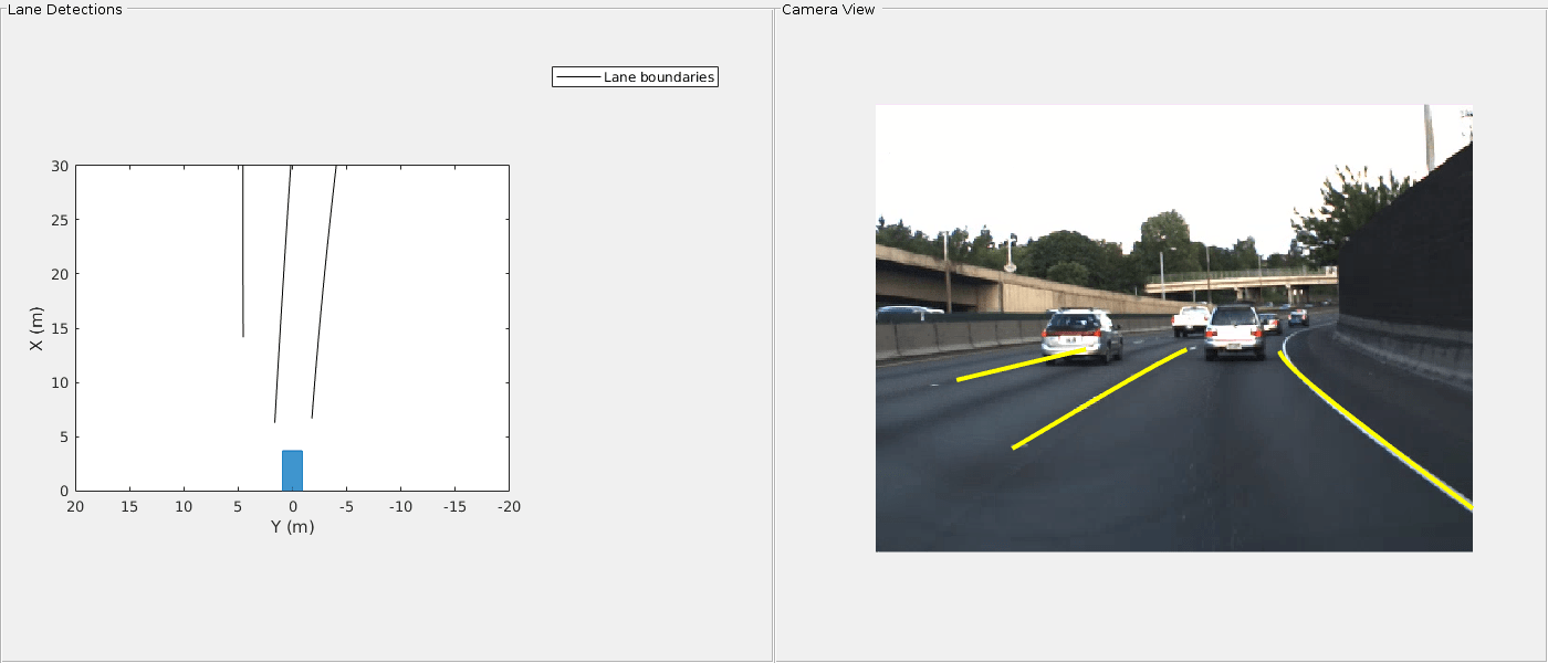
Visualize the lane boundary detections in a bird's-eye-view by using the helperPlotDetectedLanesBEV function.
currentFigure = figure(Position=[0 0 1400 600]);
hPlot = axes(uipanel(currentFigure,Position=[0 0 0.5 1],Title="Lane Detections"));
bep = birdsEyePlot(XLim=[0 30],YLim=[-20 20],Parent=hPlot);
cam = axes(uipanel(currentFigure,Position=[0.5 0 0.5 1],Title="Camera View"));
helperPlotDetectedLanesBEV(bep,cam,laneBoundaries,imds,cameraParams);
Track Lane Boundaries Using laneBoundaryTracker
Track the lane boundaries using the laneBoundaryTracker object to reduce noise and get consistent boundaries from detection and identify lane connectivity in the entire sequence, which is needed for scene generation.
Define a laneBoundaryTracker object and specify these properties:
PreProcessingFcn— Specify as thehelperPreProcessParabolicLaneBoundariesfunction,to add measurement noise using scores for each detection.PostProcessingFcn— Specify as thehelperPostProcessLaneBoundariesfunction, to obtain tracked lane boundaries as thelaneDataobject.DetectionProbability— Specify as0.8, to define the confidence in detector.
lbTracker = laneBoundaryTracker(PreProcessingFcn=@helperPreProcessParabolicLaneBoundaries, ...
    PostProcessingFcn=@helperPostProcessLaneBoundaries, ...
    DetectionProbability=0.8);
Specify the detection timestamps for the tracker. Note that the tracker requires timestamps in seconds, so you must convert the timestamps from the sensor from microseconds to seconds.
You exercise the tracker with lane boundary detections, corresponding timestamps, and specify the ShowProgress name-value pair as true to display a progress bar while tracking lane boundaries in offline.
% Load the timestamps generated by the sensor.
timeStamps = double(monocamData.timeStamp);

% The timestamps of the camera sensor are in microseconds. Convert to
% seconds and offset from the first timestamp.
tsecs = timeStamps*(10^-6);
tsecs = tsecs - tsecs(1);
Compute the measurement noise by using the detection scores. Track lane boundaries by using the step function of the laneBoundaryTracker object.
scores = cellfun(@(x) gather(x),scores,UniformOutput=false);

trackedLaneBoundaries = lbTracker(laneBoundaries,tsecs,scores,ShowProgress=true,UseSmoother=true);
Visualize the tracks on the images sequence.
helperPlotTracksOnImage(cameraParams,imds,trackedLaneBoundaries);
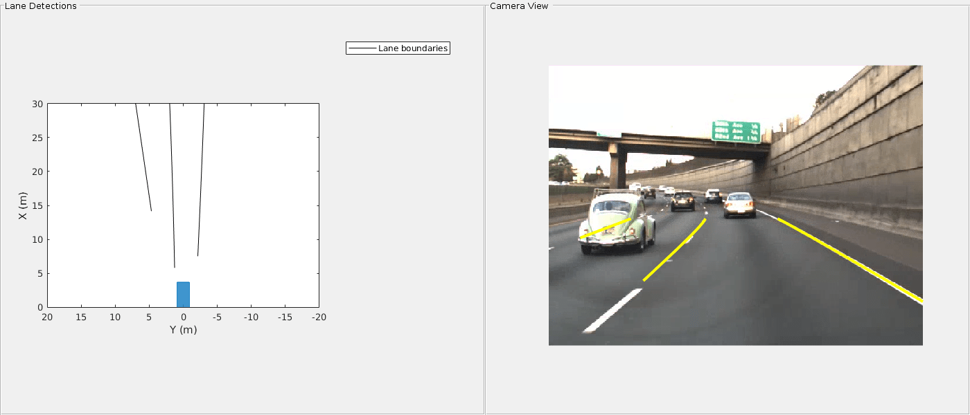
Visualize and compare the lane boundaries before and after tracking.
currentFigure = figure(Name="Compare Lane Boundaries",Position=[0 0 1400 600]);
hPlot = axes(uipanel(currentFigure,Position=[0 0 0.5 1],Title="Detected Boundaries"));
bep = birdsEyePlot(XLim=[0 30],YLim=[-20 20],Parent=hPlot);
hPlotSmooth = axes(uipanel(currentFigure,Position=[0.5 0 0.5 1],Title="Tracked Boundaries"));
bepTracked = birdsEyePlot(XLim=[0 30],YLim=[-20 20],Parent=hPlotSmooth);
helperCompareLanes(bep,laneBoundaries,bepTracked,trackedLaneBoundaries);

Display the tracked lane boundary data.
trackedLaneBoundaries
trackedLaneBoundaries =
  laneData with properties:

           TimeStamp: [714×1 double]
    LaneBoundaryData: {714×1 cell}
     LaneInformation: [714×4 struct]
            TrackIDs: {714×1 cell}
           StartTime: 0
             EndTime: 35.6422
          NumSamples: 714
Correct Lane Boundaries Using Ground Truth Labeler for Scene Generation
The tracker output can sometimes generate inconsistent tracks due to several reasons, such as failure to remove all the noise from detected lane boundaries. To generate accurate high-definition road scene from lane detections, you must troubleshoot and resolve all the issues in detections. Use the Ground Truth Labeler app to visualize and correct the noisy detections.
The app needs a groundTruthMultisignal object populated with the tracked lane boundary info. To convert the trackedLaneBoundaries to groundTruthMultisignal use the helper function helperLaneDataToLabels.
gTruth = helperLaneDataToLabels(trackedLaneBoundaries,cameraParams,imageFolderPath)
gTruth =
  groundTruthMultisignal with properties:

          DataSource: [1×1 vision.labeler.loading.ImageSequenceSource]
    LabelDefinitions: [2×7 table]
        ROILabelData: [1×1 vision.labeler.labeldata.ROILabelData]
      SceneLabelData: [0×0 vision.labeler.labeldata.SceneLabelData]
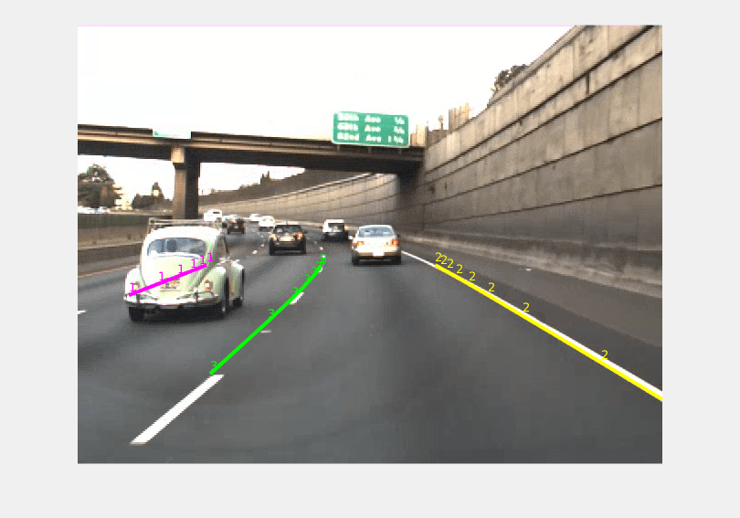
Open the Ground Truth Labeler app.
groundTruthLabeler(gTruth)
The following image shows the lane labels in the ground truth labeler app.

Using the app, you can move lane points, add new labels to missing detections or delete false labels. You can store these corrected lane labels in a laneData object to use to create scene with accurate lane detections. To convert the corrected lane boundaries in groundTruthMultisignal object into laneData object use the helperGTruthToLaneData helper function.
trackedLaneBoundaries = helperGTruthToLaneData(gTruth,cameraParams);
To generate scene from these lane detections, you require GPS or lidar data in addition to camera data. For GPS data follow Generate RoadRunner Scene Using Processed Camera Data and GPS Data example. If you have lidar data then follow Generate RoadRunner Scene Using Labeled Camera Images and Raw Lidar Data example.
Helper Functions
helperValidateBoundaryFcn — Validate the boundary model based on its intercept value.
function isGood = helperValidateBoundaryFcn(params)
    % helperValidateBoundaryFcn returns true or false if the lane boundary model fit
    % is good or bad, respectively. The value of intercept is used to
    % determine the goodness of fit.

    if ~isempty(params)
        if numel(params) == 3

            % ax^2+bx+c
            intercept = params(3);
        elseif numel(params) == 4

            % ax^3+bx^2+cx+d
            intercept = params(4);
        end

        % If the intercept is too far to the left or right of
        % ego vehicle, reject the boundary.
        isGood = intercept > -30 && intercept < 30;
    else
        isGood = false;
    end
end
helperPreProcessParabolicLaneBoundaries — Add measurement noise for each detection using confidence scores.
function [detections,time] = helperPreProcessParabolicLaneBoundaries(frameDetections,time,varargin)
    % helperPreProcessParabolicLaneBoundaries preprocess the
    % lane boundary detections to create array of
    % objectDetection objects. Update measurement noise for individual
    % detections using the confidence score.

    % Get objectDetection array using the default pre-processing function for
    % parabolic lane boundaries
    [detections,time] = laneBoundaryTracker.preProcessParabolicLaneBoundaries(frameDetections,time);

    %Scores are passed as first element of varargin array
    scores = varargin{1};

    for frameIdx = 1:numel(detections)

        frameDetections = detections{frameIdx};
        frameScores = scores{frameIdx};

        for i=1:numel(frameDetections)

            detection = frameDetections{i};

            score = frameScores(i);

            % Higher score, lower noise and vice versa. The below
            % equation captures this relation.
            noise = 1-score;

            % Measurement noise is not the same for all parameters.
            % Usually higher noise is observed in parameter of
            % parabolic model ax^2 + bx + c. The scale allows us to
            % specify the relative weight of noise for each parameter.
            scale = 1.2*[0.1 0.3 0.6];
            measurementNoise = diag(scale*noise);

            % Update measurement noise for each object
            detection.MeasurementNoise = measurementNoise;
            frameDetections{i} = detection;
        end
        detections{frameIdx} = frameDetections;
    end
end
helperPostProcessLaneBoundaries — Customize tracker output and convert lane boundaries into laneData format.
function trackedLanes = helperPostProcessLaneBoundaries(tracks,varargin)
% helperExtractLaneBoundaries returns a laneData object containing lane
% boundary detections.

% Use default post processing function and customize its output in laneData
% format.
lbTracks = laneBoundaryTracker.postProcessParabolicLaneBoundaries(tracks,varargin);
tsecs = varargin{1,4};

% Create an empty laneData object.
trackedLanes = laneData;

for frameIdx = 1:numel(lbTracks)
    boundaries = lbTracks{frameIdx};
    for laneNumber = 1:numel(boundaries)
        info(laneNumber) = struct('TrackID',boundaries{laneNumber}.TrackID); %#ok<AGROW>
    end
    if ~isempty(boundaries)
        lbs = [boundaries{:}];

        % Add boundaries to the laneData object.
        trackedLanes.addData(boundaries{1}.UpdateTime,[lbs.LaneBoundary],TrackIDs=string([lbs.TrackID]),LaneInformation=info)
    else

        % Add boundaries to the laneData object.
        trackedLanes.addData(tsecs(frameIdx),{[]},TrackIDs = {[]})
    end
end
end
helperLaneDataToLabels — Process laneData and create a groundTruthMultisignal object.
function gTruth = helperLaneDataToLabels(ld,sensor,imseqFolder)
% helperLaneDataToLabels returns a groundTruthMultisignal object from
% laneData.

% Read all the lane boundaries from the lane data object and get the
% maximum number of lanes.
allData = readData(ld,'all');
colNames = allData.Properties.VariableNames;
laneColumnNames = colNames(startsWith(colNames,"LaneBoundary")& ~(endsWith(colNames,"Info")));
maxLanes = numel(laneColumnNames);

% Create the image data source.
imseqSource = vision.labeler.loading.ImageSequenceSource;
sourceParams = struct;
sourceParams.Timestamps = seconds(ld.TimeStamp);
loadSource(imseqSource, imseqFolder,sourceParams)

% Create the label definitions.
ldc = labelDefinitionCreatorMultisignal;
labelName = "LaneBoundary";
addLabel(ldc,labelName,labelType.Line);
addAttribute(ldc,labelName,"LaneBoundaryID",attributeType.String,"1")

labelDefs = create(ldc);

% Convert lane boundaries from vehicle frame to image frame.
laneBoundaries = cell(height(allData),maxLanes);
laneBoundariesInfo = cell(height(allData),maxLanes);
for i=1:height(allData)
    boundaries = allData(i,laneColumnNames);
    for j=1:numel(boundaries)
        if ~isempty(boundaries{1,j}{1})
            p = boundaries{1,j}{1};
            x = linspace(p.XExtent(1),p.XExtent(2),6);
            y = computeBoundaryModel(p,x);
            imagePoints = vehicleToImage(sensor,[x' y']);
            laneBoundaries{i,j} = imagePoints;
            if ~isempty(ld.TrackIDs)
                trackID = allData.TrackIDs{i}(j);
                laneBoundariesInfo{i,j} = trackID;
            else
                laneBoundariesInfo{i,j} = j;
            end
        end
    end
end

laneMarkerTruth = cell(height(allData),1);

% Store the lane attributes in a struct.
for i=1:height(allData)
    boundaries = allData{i,laneColumnNames};
    pts = struct;
    for j=1:numel(boundaries)
        pts(j).Position = laneBoundaries{i,j};
        pts(j).LaneBoundaryID = laneBoundariesInfo{i,j};
    end
    laneMarkerTruth{i,1} = pts;
end

% Create the ground truth multi signal object.
labelData = table2timetable(cell2table(laneMarkerTruth, "VariableNames","LaneBoundary"),"RowTimes",seconds(ld.TimeStamp));
roiData = vision.labeler.labeldata.ROILabelData(imseqSource.SignalName, {labelData});
sceneData = vision.labeler.labeldata.SceneLabelData.empty;
gTruth = groundTruthMultisignal(imseqSource,labelDefs,roiData,sceneData);
end
See Also
monoCamera | cameraIntrinsics | trackerGNN (Sensor Fusion and Tracking Toolbox) | singer (Sensor Fusion and Tracking Toolbox) | getMapROI | roadprops | selectActorRoads
Topics
- Overview of Scenario Generation from Recorded Sensor Data
- Smooth GPS Waypoints for Ego Localization
- Generate High Definition Scene from Lane Detections and OpenStreetMap
- Generate RoadRunner Scene from Recorded Lidar Data
- Extract Vehicle Track List from Recorded Camera Data for Scenario Generation
- Generate Scenario from Actor Track Data and GPS Data