Autonomous Emergency Braking with High-Fidelity Vehicle Dynamics
This example shows how to cosimulate an autonomous emergency braking (AEB) system, designed in Simulink®, with RoadRunner Scenario. The AEB system uses a 14 degrees-of-freedom (DOF) vehicle dynamics model. This example builds on the Autonomous Emergency Braking with RoadRunner Scenario example.
Introduction
RoadRunner Scenario is an interactive editor that enables you to design scenarios for simulating and testing automated driving systems. You can place vehicles, define their paths and interactions in the scenario, and then simulate the scenario in the editor. RoadRunner Scenario supports in-editor playback for scenario visualization and connecting to other simulators, such as MATLAB® and Simulink, for cosimulation.
AEB is an advanced active safety system that helps drivers avoid or mitigate collisions with other vehicles. In an AEB system, an AEB controller specifies commands for required steering and acceleration (or braking) controls. The vehicle dynamics model receives these commands from the controller. For AEB applications, high-fidelity vehicle dynamics are very important for matching virtual simulation test results to real-world test results. This example shows you how to design and simulate an AEB system by using a 14DOF vehicle dynamics model. In this example, you use vision and radar sensors to detect objects, and a terrain sensor to detect the road surface elevation in a 3D simulation environment.
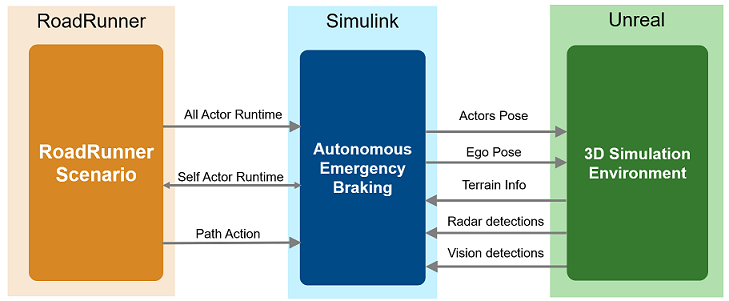
This figure shows an overview of the information exchanged between RoadRunner Scenario, a test bench model in Simulink, and the Unreal Engine® simulation environment. The Simulink model reads all actor poses and path information from RoadRunner Scenario and passes information about the ego pose and target actor poses to the Unreal Engine, which updates vehicle poses in the 3D simulation environment. The ego vehicle has attached camera, radar, and terrain sensors in the 3D simulation environment. From these sensors, the Simulink model gets camera detections, radar detections, and road surface elevation information. Using this information, the model controls the ego vehicle and writes back the new ego pose to RoadRunner Scenario.
In this example, you:
Set Up Environment — Configure MATLAB settings to interact with RoadRunner Scenario.
Explore AEB scenario — Explore the RoadRunner scene and scenario required for simulating the test bench model. This example uses the US highway scene, which contains elevated roads.
Explore Test Bench Model — The test bench has interfaces for RoadRunner Scenario, sensor fusion and tracking, decision logic, the AEB controller, high-fidelity vehicle dynamics and the metrics assessment.
Explore High-Fidelity Vehicle Dynamics — The
Vehicle Dynamicsreferenced subsystem implements transmission controls, tires, load transfer, braking, and powertrain response for a vehicle.Simulate Scenario and Analyze Results — Configure and cosimulate the AEB scenario with RoadRunner Scenario and the Unreal Engine.
This example shows cosimulation of RoadRunner Scenario with the Unreal Engine from Epic Games®.
if ~ispc
    error(['This example is only supported on Microsoft', ...
        char(174), ' Windows', char(174), '.']);
end
This example also requires you to download the Automated Driving Toolbox™ Interface for Unreal Engine 4 Projects support package. For more information on downloading and installing support packages, see Get and Manage Add-Ons.
pathToAssets = fullfile(matlabshared.supportpkg.getSupportPackageRoot, ...
    "toolbox","shared","sim3dprojects","spkg","roadrunner", ...
    "RoadRunnerProject","Assets");

if (~exist(pathToAssets,"file"))
    error("This example requires you to download and install Automated Driving Toolbox Interface for Unreal Engine 4 Projects support package.");
end
Set Up Environment
This section shows how to set up the environment to cosimulate the AEB system with high-fidelity vehicle dynamics with RoadRunner Scenario.
Specify the path to your local RoadRunner installation folder. This code shows how to configure the path for the default installation location on Windows®.
rrAppPath = "C:\Program Files\RoadRunner " + matlabRelease.Release + "\bin\win64";
Specify the path to your RoadRunner project. This code shows a sample project folder on Windows.
rrProjectPath = "C:\RR\MyProjects";
To update the path for the RoadRunner installation folder, get the root object within the settings hierarchical tree. For more information, see SettingsGroup.
s = settings;
s.roadrunner.application.InstallationFolder.TemporaryValue = rrAppPath;
Open RoadRunner using the specified path to your project.
rrApp = roadrunner(rrProjectPath);
The rrApp RoadRunner object enables you to interact with RoadRunner from the MATLAB workspace. You can open the scenario and update the scenario variables using this object. For more information on this object, see roadrunner.
Open a working copy of the files for AEB with high-fidelity dynamics project. MATLAB copies the files to an example folder so you can edit them.
openProject("AEBWithHighFidelityDynamics");
To reduce Command Window output, turn off model predictive controller (MPC) update messages.
mpcverbosity("off");
Copy the RoadRunner scene, scenario, and behavior files to the RoadRunner project.
AEBWithHighFidelityDynamicsProject = currentProject;
projectPath = convertStringsToChars(AEBWithHighFidelityDynamicsProject.RootFolder);
projectRootFolder = projectPath(1:find(projectPath=='\',1,'last')-1);

copyfile(fullfile(pathToAssets,"/Markings/*.rrmeta"), fullfile(rrProjectPath,"Assets/Markings"),'f')
copyfile(fullfile(pathToAssets,"/Signs/US/*.rrmeta"), fullfile(rrProjectPath,"Assets/Signs/US"),'f')
copyfile(fullfile(projectRootFolder,"AEBTestScenarios/RoadRunner/Scenes"),fullfile(rrProjectPath,"Scenes"),'f')
copyfile(fullfile(projectRootFolder,"AEBTestScenarios/RoadRunner/Scenarios"),fullfile(rrProjectPath,"Scenarios"),'f')
copyfile(fullfile(projectRootFolder,"AEBWithHighFidelityDynamics/TestBench/AEBHighFidelityDynamics.rrbehavior.rrmeta"),fullfile(rrProjectPath,"Assets","Behaviors"),'f')
Explore AEB Scenario
This example uses the scenario_01_USHighway_EntryRamp scenario authored using RoadRunner Scenario. The scenario contains a US highway scene, which has elevated roads and entry and exit ramps. The scene is compatible with the AEBWithHighFidelityDynamicsTestBench model. For more information on the USHighway scene, see US Highway. Open the scene.
openScene(rrApp,"USHighway.rrscene");

scenario_01_USHighway_EntryRamp.rrscenario is an open-loop scenario containing an ego vehicle, a target vehicle, and a pedestrian actor on a US highway road. In this scenario, a target vehicle cuts into the ego lane on an entry ramp and collides with the ego vehicle. Both the ego and target vehicles follow predefined paths in the scenario. Open scenario_01_USHighway_EntryRamp in the USHighway Scene.
openScenario(rrApp,"scenario_01_USHighway_EntryRamp.rrscenario");

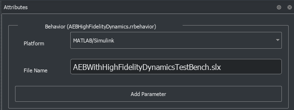
To simulate the AEB with high-fidelity vehicle dynamics behavior, use the AEBHighFidelityDynamics.rrbehavior.rrmeta file to assign custom behavior to the ego vehicle.
Connect to the RoadRunner Scenario server for cosimulation using the createSimulation function, and enable data logging.
rrSim = createSimulation(rrApp);
set(rrSim,Logging="on");
rrSim is a ScenarioSimulation object. Use this object to set variables and read scenarios and map-related information.
The AEB with high-fidelity vehicle dynamics application is designed to run at a step size of 0.05 seconds. Set the simulation step size of RoadRunner Scenario to 0.05 seconds.
Ts = 0.05;
set(rrSim,StepSize=Ts);
Explore Test Bench Model
In this example, you use a system-level simulation test bench model to simulate and test the behavior of autonomous emergency braking with the high-fidelity dynamics model. Open the test bench model.
modelName = "AEBWithHighFidelityDynamicsTestBench";
open_system(modelName)

The test bench model contains RoadRunner Scenario blocks, which configure, read from, and write to RoadRunner Scenario, as well as these modules:
Pack Actor Poses— MATLAB System object™ that provides inputs to the vehicles in the 3D simulation environment from driving-scenario-compatible poses of target actors read from RoadRunner Scenario.Generate EgoReference Path— MATLAB System object that calculates the reference path attributes using the path information from RoadRunner Scenario.Sensors and Actors— Subsystem that specifies and updates the 3D simulation environment along with the vision, radar, and terrain sensors used for simulation.Sensor Fusion and Tracking— Algorithm model that fuses vehicle detections from the vision with those from the radar sensor.AEB Decision Logic— Algorithm model that specifies the lateral and longitudinal decision logic that provides the most important object (MIO) related information and ego vehicle reference path information to the controller.AEB Controller— Algorithm model that specifies the steering angle and acceleration controls.Vehicle Dynamics— Subsystem that specifies the 14DOF dynamics model of the ego vehicle.Metrics Assessment— Subsystem that assesses system-level behavior.
The Sensor Fusion and Tracking, AEB Decision Logic, and AEB Controller algorithm models and Metrics Assessment subsystem are reused from the Autonomous Emergency Braking with Sensor Fusion example. The Vehicle Dynamics referenced subsystem is reused from the Autonomous Emergency Braking with Vehicle Variants example. This example focuses on the RoadRunner Scenario blocks and the Sensors and Actors subsystem interacting with the 14DOF vehicle dynamics model.
RoadRunner Scenario Blocks
The RoadRunner Scenario blocks consist of:
RoadRunner Scenario— Defines the interface for an actor model.Self Actor Runtime Reader— RoadRunner Scenario Reader block that reads ego actor runtime information.All Actor Runtime— RoadRunner Scenario Reader block that reads the runtime information of all the vehicles.Path Action— RoadRunner Scenario Reader block that reads the reference path of the ego vehicle.Self Actor Runtime Writer— RoadRunner Scenario Writer block that writes the ego vehicle runtime to RoadRunner Scenario.
Sensors and Actors
The Sensors and Actors subsystem specifies sensors and vehicles in the 3D simulation environment. The target actors in the 3D simulation environment update their poses using RoadRunner Scenario. The ego vehicle has attached the vision and radar sensors, which provide vision and radar detections from 3D simulation environment to the Sensor Fusion and Tracking algorithm model of the test bench for further processing. The ego vehicle has also attached the terrain sensor, which does ray tracing to detect the terrain below the tires. Open the Sensors and Actors subsystem.
open_system("AEBWithHighFidelityDynamicsTestBench/Sensors and Actors")

The Simulation 3D Scene Configuration block specifies the scene and the road network. Its SceneName parameter value is US highway.
The actor positions are specified by these parts of the subsystem:
The
Ego ActorandTarget Actorsinputs specify the current positions of the ego and target actors, respectively, in RoadRunner Scenario.
The World To Vehicle block converts actor poses from world coordinates to the vehicle coordinates of the input ego vehicle.
The
HelperConvertDSPoseToSim3Dblock converts the Driving Scenario compatible pose from RoadRunner Scenario to theX,Y, andYawcoordinates used by the 3D simulation environment.The Simulation 3D Vehicle with Ground Following implements a vehicle at the specified position in the 3D simulation environment.
The Simulation 3D Pedestrian implements a pedestrian in a 3D simulation environment.
The
Pack Vehicle Datablock packs the ego vehicle dynamics information compatible for the Simulation 3D Vehicle.The Simulation 3D Vehicle (Vehicle Dynamics Blockset) block implements a vehicle with four wheels in the 3D simulation environment.
These sensors have a Parent Name parameter value of Simulation 3D Vehicle with Ground Following, assigning them to the ego vehicle:
The Simulation 3D Vision Detection Generator block generates detections from camera measurements taken by a vision sensor mounted on an ego vehicle in a 3D simulation environment.
The Simulation 3D Probabilistic Radar Configuration block configures the probabilistic radar signatures for actors in a 3D simulation environment.
The Simulation 3D Probabilistic Radar block generates object detections based on a statistical model. The Detection Clustering block clusters all the detections generated by a radar sensor.
The Simulation 3D Terrain Sensor (Vehicle Dynamics Blockset) implements a multipoint terrain sensor in a 3D simulation environment. The
Pack Wheels Elevation Infosubsystem extracts the z-coordinate values of wheels of the ego vehicle in the order of front left, front right, rear left, and rear right wheel. The Vehicle Dynamics subsystem uses the wheel elevation information to estimate the ego orientation, which is crucial while traveling on the elevated roads such as entry ramp.
Explore High-Fidelity Vehicle Dynamics
The Vehicle Dynamics subsystem implements transmission controls, tires, load transfer, braking, and powertrain response for a vehicle. Open the Vehicle Dynamics subsystem.
open_system("AEBWithHighFidelityDynamicsTestBench/Vehicle Dynamics");
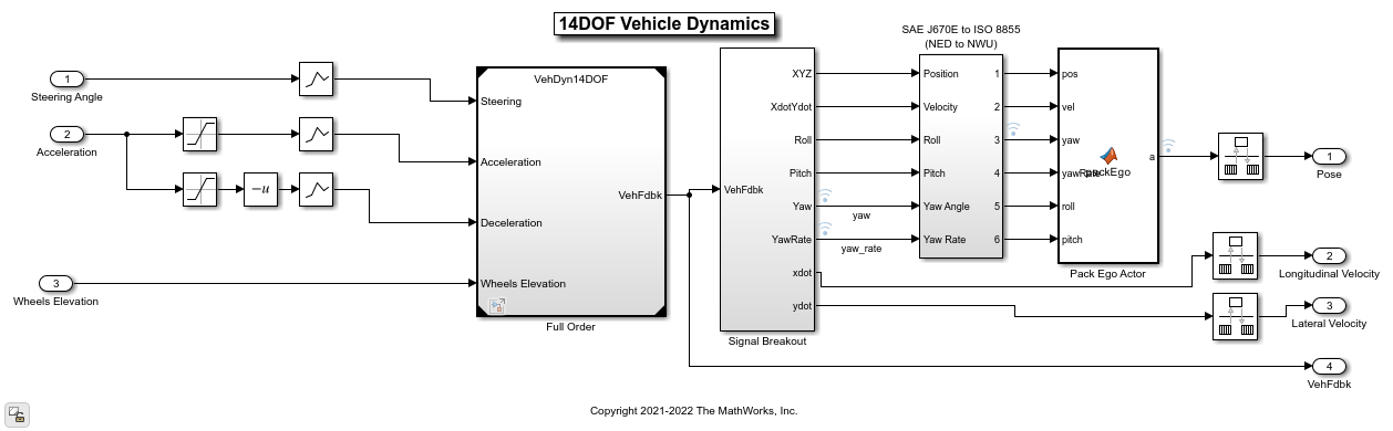
The Vehicle Dynamics subsystem contains the VehDyn14DOF reference model, which has the Input Routing, Driver Commands, Controllers, and Environment subsystems. Open the VehDyn14DOF reference model.
open_system("VehDyn14DOF")

The VehDyn14DOF reference model has a Passenger Vehicle subsystem that contains the Engine, Steering and Driveline, Pedal cluster and Cabin, and Chassis and Tires subsystems. Open the Passenger Vehicle subsystem.
open_system("VehDyn14DOF/Passenger Vehicle")
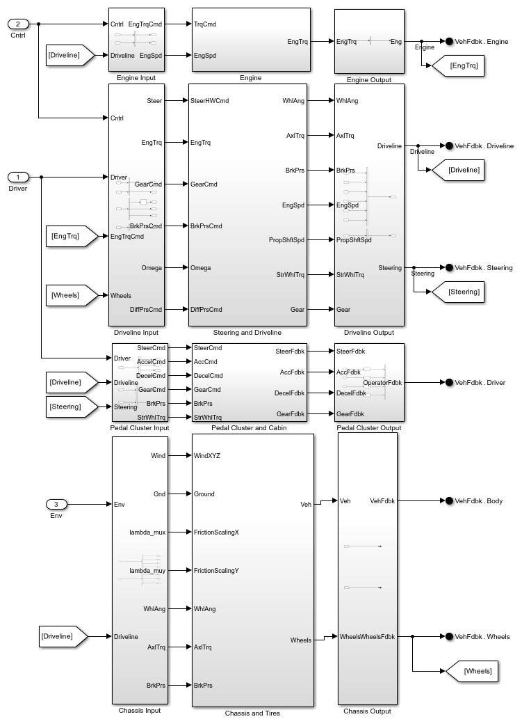
The Passenger Vehicle subsystem contains these subsystems:
Engine— TheEnginesubsystem contains a Mapped SI Engine block to model a spark-ignition engine by using power, air mass flow, fuel flow, exhaust temperature, efficiency, and emission performance lookup tables. For more details, see Mapped SI Engine (Vehicle Dynamics Blockset).
Steering and Driveline— TheSteering and Drivelinesubsystem uses a Kinematic Steering block with theTypeparameter set toAckerman. For more details, see Kinematic Steering (Vehicle Dynamics Blockset). The transmission is modeled using the Ideal Fixed Gear Transmission block. For more details on the transmission, see Ideal Fixed Gear Transmission (Vehicle Dynamics Blockset). TheDriveline Modelis a variant subsystem that contains four variants:Rear Wheel Drive,Front Wheel Drive,All Wheel Drive, and the defaultRear Wheel Drive Active Differential. TheBrake Hydraulicssubsystem converts the brake command to the actual brake pressure on the pedal.
Pedal Cluster and Cabin— ThePedal Cluster and Cabinsubsystem is a placeholder for introducing faults, detailed actuator behavior, and interactions of other systems with a human interface, such as changes in power steering and braking assistance.
Chassis and Tires— TheChassis and Tiressubsystem has theVehiclesubsystem,Wheels and Tiressubsystem, andSuspensionvariant subsystem. TheVehiclesubsystem has a variant subsystem to select between a3DOFand a6DOFvehicle body. TheWheels and Tiressubsystem has aVDBSsubsystem containing the variant subsystemTires, which selects between theMagic Formula Tires,Fiala Tires,Magic Formula Vector Tires(default), andFiala Tires Vectorvariants. TheSuspensionvariant subsystem has six variants of suspension models:Double Wishbone Suspensionthat uses Independent Suspension - Double Wishbone (Vehicle Dynamics Blockset),Independent Mapped Front Suspension Mapped Solid Axle Rear Suspensionthat uses Independent Suspension - Mapped (Vehicle Dynamics Blockset) for front suspension and Solid Axle Suspension - Mapped (Vehicle Dynamics Blockset) for rear suspension,MacPherson Front Suspension Solid Axle Rear Suspensionuses the Independent Suspension - MacPherson (Vehicle Dynamics Blockset) for front suspension and solid axle for rear suspension,MacPherson Suspensionuses independent MacPherson suspension,Mapped Suspensionuses the independent Mapped suspension,Kinematics and Compliance Independent Suspensionuses the Independent Suspension - K and C (Vehicle Dynamics Blockset) (default).
Simulate Scenario and Analyze Results
The higher order 14DOF vehicle model enables you to more realistically reflect nonlinear dynamics and effects including transmission controls, tires, load transfer, braking, and powertrain response. This example uses the helperSLAEBWithHighFidelityDynamicsSetup helper function to set up the ego and target actor profiles along with the sensor parameters. These values are scenario dependent and can change based on the selected scenario. Configure the model with the scenario_01_USHighway_EntryRamp scenario.
helperSLAEBWithHighFidelityDynamicsSetup(rrApp,rrSim,scenarioFileName="scenario_01_USHighway_EntryRamp");
This model can take a couple of minutes to update the diagram when you compile it for the first time. Update the model before running the simulation.
set_param("AEBWithHighFidelityDynamicsTestBench",SimulationCommand="update");
Simulate the scenario and observe how the AEB system avoids collision.
set(rrSim,SimulationCommand="Start")
while strcmp(get(rrSim,"SimulationStatus"),"Running")
    pause(1)
end

This animation shows the visualization in the Unreal Engine. Notice that when the target vehicle cuts into the ego lane on a ramp, the ego vehicle applies brakes to avoid collision. You can visualize the state of brakes using brake lights.
To analyze the AEB performance, use the helperPlotAEBResults function to plot the simulation results.
helperPlotAEBResults(logsout,"scenario_01_USHighway_EntryRamp");

TTC vs. Stopping Time — Compares the time-to-collision (TTC) and the stopping times for the forward collision warning (FCW), first stage partial brake, second stage partial brake, and full brake, respectively. For more information about multi-stage partial braking, see the Autonomous Emergency Braking with Sensor Fusion example.
FCW and AEB Status — Displays the FCW and AEB activation status based on the comparison results from the first plot.
Ego Car Acceleration — Shows the longitudinal and lateral acceleration of the ego vehicle.
Ego Car Yaw and Yaw Rate — Shows the yaw and yaw rate of the ego vehicle.
Ego Car Velocity — Shows the longitudinal velocity of the ego vehicle.
Headway — Shows the headway between the ego vehicle and the MIO.
To analyze the longitudinal and lateral dynamics results, use the helperPlot14DOFVehicleResults function to plot the longitudinal and lateral simulation results.
[hFigLongResults,hFigLatResults] = helperPlot14DOFVehicleResults(logsout,scenarioFileName);


From the Longitudinal Results plots, you can observe the acceleration and deceleration input commands and corresponding outputs from the high-fidelity vehicle dynamics model, such as the ego car velocity, longitudinal acceleration, and brake pressures at the four wheels. These plots enable you to analyze the longitudinal behavior of the vehicle.
From the Lateral Results plots, you can observe the steering input commands and corresponding outputs such as the yaw rate, lateral acceleration, and gear commands. These plots enable you to analyze the lateral behavior of the vehicle.
For an ego vehicle traveling at higher speeds, you can also plot tire forces, suspension forces, engine speed, and tire speeds for a more in-depth analysis.
close(hFigLongResults);
close(hFigLatResults);
This example also provides an additional scenario, scenario_02_USHighway_Pedestrian, which is compatible with the AEBWithHighFidelityDynamicsTestBench model. This scenario has a pedestrian actor that follows a predefined path, and it has been created using the RoadRunner Scenario. You can configure the AEBWithHighFidelityDynamicsTestBench model and workspace to simulate this scenario using the helperSLAEBWithHighFidelityDynamicsSetup function.
To configure the test bench to simulate the scenario_02_USHighway_Pedestrian scenario, enter this command.
helperSLAEBWithHighFidelityDynamicsSetup(rrApp,rrSim,scenarioFileName="scenario_02_USHighway_Pedestrian");
This scenario enables you to analyze the longitudinal dynamics of the 14DOF vehicle model. For new scenarios, you must specify the initial gear value for the transmission controller that provides inputs to the Passenger Vehicle subsystem. To set the initial gear to 0, enter this command.
set_param("VehDyn14DOF/Controllers/Transmission Controller/PRNDL Controller/Transmission Controller PRNDL",GearInit='0');
When you are done with this example, enable MPC update messages.
mpcverbosity("on");
See Also
Blocks
- World To Vehicle | Simulation 3D Pedestrian | Simulation 3D Terrain Sensor (Vehicle Dynamics Blockset) | Simulation 3D Probabilistic Radar | Simulation 3D Vision Detection Generator | RoadRunner Scenario | RoadRunner Scenario Reader | RoadRunner Scenario Writer
Related Topics
- Autonomous Emergency Braking with Sensor Fusion
- Autonomous Emergency Braking with Vehicle Variants
- Automate Testing for Autonomous Emergency Braking
- Automate Testing for Scenario Variants of AEB System
- Autonomous Emergency Braking with RoadRunner Scenario
- Lateral Offset Follower with High-Fidelity Vehicle Dynamics
Select a Web Site
Choose a web site to get translated content where available and see local events and offers. Based on your location, we recommend that you select: United States.
You can also select a web site from the following list
Americas
- América Latina (Español)
- Canada (English)
- United States (English)
Europe
- Belgium (English)
- Denmark (English)
- Deutschland (Deutsch)
- España (Español)
- Finland (English)
- France (Français)
- Ireland (English)
- Italia (Italiano)
- Luxembourg (English)
- Netherlands (English)
- Norway (English)
- Österreich (Deutsch)
- Portugal (English)
- Sweden (English)
- Switzerland
- United Kingdom (English)
Asia Pacific
- Australia (English)
- India (English)
- New Zealand (English)
- 中国
- 日本Japanese (日本語)
- 한국Korean (한국어)