Simulation 3D Pedestrian
Libraries:
Automated Driving Toolbox /
Simulation 3D
Simulink 3D Animation /
Simulation 3D /
Actors
Description
Note
Simulating models with the Simulation 3D Pedestrian block requires Simulink® 3D Animation™.
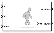
The Simulation 3D Pedestrian block implements a pedestrian in a 3D simulation environment. The block uses the input (X, Y) position and yaw angle of the pedestrian to adjust the elevation, roll angle, and pitch angle so that the pedestrian follows the ground terrain. The block determines the pedestrian velocity and heading and adjusts the movement to be idle, walk, or run, appropriately.
To use this block, ensure that the Simulation 3D Scene Configuration block
is in your model. If you set the Sample time parameter of the
Simulation 3D Pedestrian block to -1, the block inherits
the sample time specified in the Simulation 3D Scene Configuration
block.
The Coordinate system parameter of the block specifies how the actor transformations are applied in the 3D environment. The output of the block also follows the specified coordinate system.
By default, the block input uses the pedestrian Z-up right-handed (RH) Cartesian coordinate system defined in SAE J670 [1] and ISO 8855 [2]. The coordinate system is inertial and initially aligned with the pedestrian feet:
The X-axis is along the longitudinal axis of the pedestrian and points forward.
The Y-axis is along the lateral axis of the pedestrian and points to the left.
The Z-axis points upward.
The yaw, pitch, and roll angles of the Z-axis, Y-axis, and X-axis, respectively, are positive in the clockwise directions, when looking in the positive directions of these axes. Pedestrians are placed in the world coordinate system of the scenes. For more details, see Coordinate Systems for Unreal Engine Simulation in Automated Driving Toolbox.
Examples
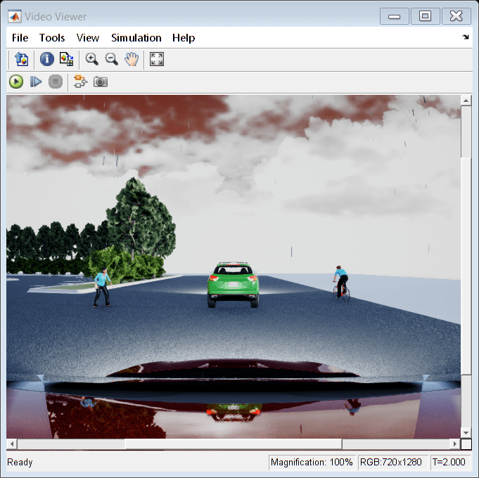
Simulate Simple Driving Scenario and Sensor in Unreal Engine Environment
Learn the basics of configuring and simulating scenes, vehicles, and sensors in a virtual environment rendered using the Unreal Engine® from Epic Games®.
Ports
Input
Output
Parameters
References
[1] Vehicle Dynamics Standards Committee. Vehicle Dynamics Terminology. SAE J670. Warrendale, PA: Society of Automotive Engineers, 2008.
[2] Technical Committee. Road vehicles — Vehicle dynamics and road-holding ability — Vocabulary. ISO 8855:2011. Geneva, Switzerland: International Organization for Standardization, 2011.