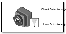
Simulation 3D Vision Detection Generator
Detect objects and lanes from measurements in 3D simulation environment
Libraries:
Automated Driving Toolbox /
Simulation 3D
Description
Note
Simulating models with the Simulation 3D Vision Detection Generator block requires Simulink® 3D Animation™.
The Simulation 3D Vision Detection Generator block generates detections from camera measurements taken by a vision sensor mounted on an ego vehicle in a 3D simulation environment. This environment is rendered using the Unreal Engine® from Epic Games®. The block derives detections from simulated actor poses that are based on cuboid (box-shaped) representations of the actors in the scenario. For more details, see Algorithms.
The block generates detections at intervals equal to the sensor update interval. Detections are referenced to the coordinate system of the sensor. The block can simulate real detections that have added random noise and also generate false positive detections. A statistical model generates the measurement noise, true detections, and false positives. To control the random numbers that the statistical model generates, use the random number generator settings on the Measurements tab of the block.
If you set Sample time to -1, the block uses the
sample time specified in the Simulation 3D Scene Configuration block. To use
this sensor, you must include a Simulation 3D Scene Configuration block in your
model.
Tip
The Simulation 3D Scene Configuration block must execute before the Simulation 3D Vision Detection Generator block. That way, the Unreal Engine 3D visualization environment prepares the data before the Simulation 3D Vision Detection Generator block receives it. To check the block execution order, right-click the blocks and select Properties. On the General tab, confirm these Priority settings:
Simulation 3D Scene Configuration —
0Simulation 3D Vision Detection Generator —
1
For more information about execution order, see How Unreal Engine Simulation for Automated Driving Works.
Examples

Simulate Vision and Radar Sensors in Unreal Engine Environment
Implement a synthetic data simulation for tracking and sensor fusion using Simulink and the Unreal Engine simulation environment.
Limitations
The Simulation 3D Vision Detection Generator block does not detect lanes in the Virtual Mcity scene.
Ports
Output
Object detections, returned as a Simulink bus containing a MATLAB structure. For more details about buses, see Create Nonvirtual Buses (Simulink). The structure has the form shown in this table.
| Field | Description | Type |
|---|---|---|
NumDetections | Number of detections | Integer |
IsValidTime | False when updates are requested at times that are between block invocation intervals | Boolean |
Detections | Object detections | Array of object detection structures of length set by the
Maximum number of reported detections parameter. Only
NumDetections of these detections are actual
detections. |
The object detection structure contains these properties.
| Property | Definition |
|---|---|
Time | Measurement time |
Measurement | Object measurements |
MeasurementNoise | Measurement noise covariance matrix |
SensorIndex | Unique ID of the sensor |
ObjectClassID | Object classification |
MeasurementParameters | Parameters used by initialization functions of nonlinear Kalman tracking filters |
ObjectAttributes | Additional information passed to tracker |
The Measurement field reports the position and velocity of a
measurement in the coordinate system of the sensor. This field is a real-valued column
vector of the form [x; y; z;
vx; vy; vz]. The
MeasurementNoise field is a 6-by-6 matrix that reports the
measurement noise covariance for each coordinate in the Measurement
field.
The MeasurementParameters field is a structure that has these
fields.
| Parameter | Definition |
|---|---|
Frame | Enumerated type indicating the frame used to report measurements. The
Simulation 3D Vision Detection Generator block reports
detections in sensor Cartesian coordinates, which is a rectangular
coordinate frame. Therefore, for this block, Frame is
always set to 'rectangular'. |
OriginPosition | Offset of the sensor origin from the ego vehicle origin, returned as a vector of the form [x, y, z]. The block derives these values from the x, y, and z mounting position of the sensor. For more details, see the Mounting parameters of this block. |
Orientation | Orientation of the sensor coordinate frame with respect to the ego vehicle coordinate frame, returned as a 3-by-3 real-valued orthonormal matrix. The block derives these values from the yaw, pitch, and roll mounting orientation of the sensor. For more details, see the Mounting parameters of this block. |
HasVelocity | Indicates whether measurements contain velocity. |
The ObjectClassID property of each detection has a value that
corresponds to an object ID. The table shows the object IDs used in the default scenes
that you can select from the Simulation 3D Scene
Configuration block. If you are using a custom scene, in the Unreal® Editor, you can assign new object types to unused IDs. For more details,
see Apply Labels to Unreal Scene Elements for Semantic Segmentation and Object Detection. If a scene
contains an object that does not have an assigned ID, that object is assigned an ID of
0. The block detects objects only of class
Vehicle, such as vehicles created by using Simulation 3D
Vehicle with Ground Following blocks, or of class
Road.
| ID | Type |
|---|---|
0 | None/default |
1 | Building |
2 | Not used |
3 | Other |
4 | Pedestrians |
5 | Pole |
6 | Lane markings |
7 | Road |
8 | Sidewalk |
9 | Vegetation |
10 | Vehicle |
11 | Not used |
12 | Generic traffic sign |
13 | Stop sign |
14 | Yield sign |
15 | Speed limit sign |
16 | Weight limit sign |
17-18 | Not used |
19 | Left and right arrow warning sign |
20 | Left chevron warning sign |
21 | Right chevron warning sign |
22 | Not used |
23 | Right one-way sign |
24 | Not used |
25 | School bus only sign |
26-38 | Not used |
39 | Crosswalk sign |
40 | Not used |
41 | Traffic signal |
42 | Curve right warning sign |
43 | Curve left warning sign |
44 | Up right arrow warning sign |
45-47 | Not used |
48 | Railroad crossing sign |
49 | Street sign |
50 | Roundabout warning sign |
51 | Fire hydrant |
52 | Exit sign |
53 | Bike lane sign |
54-56 | Not used |
57 | Sky |
58 | Curb |
59 | Flyover ramp |
60 | Road guard rail |
| 61 | Bicyclist |
62-66 | Not used |
67 | Deer |
68-70 | Not used |
71 | Barricade |
72 | Motorcycle |
73-255 | Not used |
The ObjectAttributes property of each detection is a
structure that has these fields.
| Field | Definition |
|---|---|
TargetIndex | Identifier of the actor, ActorID, that generated the
detection. For false alarms, this value is negative. |
Dependencies
To enable this output port, on the Parameters tab, set the
Types of detections generated by sensor parameter to
Lanes and objects, Objects
only, or Lanes with occlusion.
Lane boundary detections, returned as a Simulink bus containing a MATLAB structure. The structure has these fields.
| Field | Description | Type |
|---|---|---|
Time | Lane detection time | Real scalar |
IsValidTime | False when updates are requested at times that are between block invocation intervals | Boolean |
SensorIndex | Unique identifier of sensor | Positive integer |
NumLaneBoundaries | Number of lane boundary detections | Nonnegative integer |
LaneBoundaries | Lane boundary detections starting from the leftmost lane with respect to the ego vehicle. | Array of clothoidLaneBoundary objects |
Dependencies
To enable this output port, on the Parameters tab, set the
Types of detections generated by sensor parameter to
Lanes and objects, Lanes
only, or Lanes with occlusion.
Ground truth of actor poses in the simulation environment, returned as a Simulink bus containing a MATLAB structure.
The structure has these fields.
| Field | Description | Type |
|---|---|---|
NumActors | Number of actors | Nonnegative integer |
Time | Current simulation time | Real-valued scalar |
Actors | Actor poses | NumActors-length array of actor pose structures |
Each actor pose structure in Actors has these fields.
| Field | Description |
|---|---|
ActorID | Scenario-defined actor identifier, specified as a positive integer. |
Position | Position of actor, specified as a real-valued vector of the form [x y z]. Units are in meters. |
Velocity | Velocity (v) of actor in the x- y-, and z-directions, specified as a real-valued vector of the form [vx vy vz]. Units are in meters per second. |
Roll | Roll angle of actor, specified as a real-valued scalar. Units are in degrees. |
Pitch | Pitch angle of actor, specified as a real-valued scalar. Units are in degrees. |
Yaw | Yaw angle of actor, specified as a real-valued scalar. Units are in degrees. |
AngularVelocity | Angular velocity (ω) of actor in the x-, y-, and z-directions, specified as a real-valued vector of the form [ωx ωy ωz]. Units are in degrees per second. |
The pose of the ego vehicle is excluded from the Actors
array.
Dependencies
To enable this output port, on the Ground Truth tab, select the Output actor truth parameter.
Ground truth of lane boundaries in the simulation environment, returned as a Simulink bus containing a MATLAB structure.
The structure has these fields.
| Field | Description | Type |
|---|---|---|
NumLaneBoundaries | Number of lane boundaries | Nonnegative integer |
Time | Current simulation time | Real scalar |
LaneBoundaries | Lane boundaries starting from the leftmost lane with respect to the ego vehicle. | NumLaneBoundaries-length array of lane boundary structures |
Each lane boundary structure in LaneBoundaries has these
fields.
| Field | Description |
| Lane boundary coordinates, specified as a real-valued N-by-3 matrix, where N is the number of lane boundary coordinates. Lane boundary coordinates define the position of points on the boundary at specified longitudinal distances away from the ego vehicle, along the center of the road.
This matrix also includes the boundary coordinates at zero distance from the ego vehicle. These coordinates are to the left and right of the ego-vehicle origin, which is located under the center of the rear axle. Units are in meters. |
| Lane boundary curvature at each row of the Coordinates matrix, specified
as a real-valued N-by-1 vector. N is the
number of lane boundary coordinates. Units are in radians per meter. |
| Derivative of lane boundary curvature at each row of the Coordinates
matrix, specified as a real-valued N-by-1 vector.
N is the number of lane boundary coordinates. Units are
in radians per square meter. |
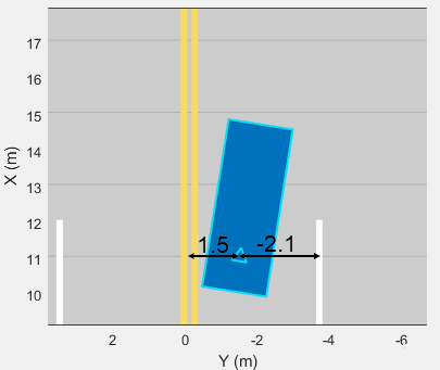
| Initial lane boundary heading angle, specified as a real scalar. The heading angle of the lane boundary is relative to the ego vehicle heading. Units are in degrees. |
| Lateral offset of the ego vehicle position from the lane boundary, specified as a real scalar. An offset to a lane boundary to the left of the ego vehicle is positive. An offset to the right of the ego vehicle is negative. Units are in meters. In this image, the ego vehicle is offset 1.5 meters from the left lane and 2.1 meters from the right lane.
|
| Type of lane boundary marking, specified as one of these values:
|
| Saturation strength of the lane boundary marking, specified as a real scalar from 0 to
1. A value of |
| Lane boundary width, specified as a positive real scalar. In a double-line lane marker, the same width is used for both lines and for the space between lines. Units are in meters. |
| Length of dash in dashed lines, specified as a positive real scalar. In a double-line lane marker, the same length is used for both lines. |
| Length of space between dashes in dashed lines, specified as a positive real scalar. In a dashed double-line lane marker, the same space is used for both lines. |
The number of returned lane boundary structures depends on the Maximum number of reported lanes parameter value.
Dependencies
To enable this output port, on the Ground Truth tab, select the Output lane truth parameter.
Parameters
Tips
The sensor is unable to detect lanes and objects from vantage points too close to the ground. After mounting the sensor block to a vehicle by using the Parent name parameter, set the Mounting location parameter to one of the predefined mounting locations on the vehicle.
If you leave Mounting location set to
Origin, which mounts the sensor on the ground below the vehicle center, then specify an offset that is at least 0.1 meter above the ground. Select Specify offset, and in the Relative translation [X, Y, Z] (m) parameter, set a Z value of at least0.1.To visualize detections and sensor coverage areas, use the Bird's-Eye Scope. See Visualize Sensor Data from Unreal Engine Simulation Environment.
Because the Unreal Engine can take a long time to start between simulations, consider logging the signals that the sensors output. See Mark Signals for Logging (Simulink).
Algorithms
To generate detections, the Simulation 3D Vision Detection Generator block
feeds the actor and lane ground truth data that is read from the Unreal Engine simulation environment to a Vision Detection
Generator block. This block returns detections that are based on cuboid, or
box-shaped, representations of the actors. The physical dimensions of detected actors are not
based on their dimensions in the Unreal Engine environment. Instead, they are based on the default values set in the
Actor Profiles parameter tab of the Vision Detection
Generator block, as seen when the Select method to specify actor
profiles parameter is set to Parameters. With these
defaults, all actors are approximately the size of a sedan. If you return detections that have
occlusions, then the occlusions are based on all actors being of this one size.