Map Environment for Motion Planning Using UAV Lidar
This example demonstrates how to use a UAV, equipped with a lidar sensor, to map an environment in a 3D occupancy map. That generated occupancy map can then be used to execute motion planning. The UAV follows a specified trajectory through the environment. Knowledge of the position of the UAV and the point clouds obtained at corresponding locations are used to build a map of the environment. The pose of the UAV is assumed to be completely known throughout the mapping flight; this is also known as mapping with known poses. The generated map is used for motion planning. The goal of the motion planning is to plan the path of a UAV in an apartment complex where it is used to drop off packages, delivered at the gate, to a desired rooftop location within the complex.
The East-North-Up (ENU) coordinate system is used throughout this example.
Table of Contents
Create Scenario
Create a simple uavScenario to build a representation of a simple apartment complex scene. During the scenario simulation, the scene will be used to create simulate lidar data points.
Specify the time and update rate of the simulation. In this case, the simulated flight takes 60 seconds and the simulation is updated at 2 Hz.
close all
close all hidden

simTime = 60;    % in seconds
updateRate = 2;  % in Hz
scene = uavScenario("UpdateRate",updateRate,"StopTime",simTime);
Add static meshes to the scenario to represent different buildings in the environment. We define each building with a rectangular footprint and varying height. All the coordinates are in meters.
% Floor
addMesh(scene, "Polygon",{[0 0;80 0;80 80;40 80;40 40;0 40],[-1 0]},[0.3 0.3 0.3]);

% Features
addMesh(scene, "Polygon",{[10 0;30 0;30 20;10 20],[0 40]},[0.4660 0.6740 0.1880]);     % Building 1
addMesh(scene, "Polygon",{[45 0;80 0;80 30;45 30],[0 60]},[0.9290 0.6980 0.1250]);     % Building 2
addMesh(scene, "Polygon",{[0 35;10 35;10 40;0 40],[0 5]},[0 0.5 0]);                   % Generator Room
addMesh(scene, "Polygon",{[50 40;80 40;80 70;50 70],[0 5]},[0 0.4470 0.7410]);         % Swimming Pool
addMesh(scene, "Polygon",{[0 0;2 0;2 4;0 4],[0 3]},[0.6350 0.0780 0.1840]);            % Security Room
View the created scenario in 3D.
show3D(scene);
axis equal
view([-115 20])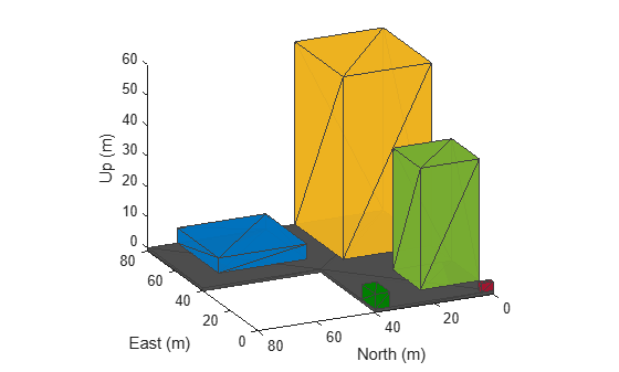
Create Mapping Trajectory
Specify the trajectory that the UAV follows for mapping the environment. Specify waypoints and assign orientation for each waypoint.
The complete pose vector for UAV is as follows
pose = [x y z a b c d]
x, y and z specify the position of the UAV with respect to the scenario's frame of reference. a, b, c and d are the parts of the quaternion number that specifies the orientation of the UAV with respect to the scenario's reference frame. a is the real part of the quaternion.
% Waypoints
x = -20:80;
y = -20:80;
z = 100*ones(1,length(x));

waypoints = [x' y' z'];
Specify the orientation as Euler angles (in radians) and convert the Euler angles to a quaternion:
orientation_eul = [0 0 0];
orientation_quat = quaternion(eul2quat(orientation_eul));
orientation_vec = repmat(orientation_quat,length(x),1);
Specify time vector.
time = 0:(simTime/(length(x)-1)):simTime;
Generate trajectory from the specified waypoints and orientations using waypointTrajectory system object. Specify the reference frame as 'ENU'.
trajectory = waypointTrajectory("Waypoints",waypoints,"Orientation",orientation_vec, ...
    "SampleRate",updateRate,"ReferenceFrame","ENU","TimeOfArrival",time);
Specify the initial pose of the UAV.
initial_pose = [-20 -20 100 1 0 0 0];
Create UAV Platform
Create a uavPlatform object and update the scenario with a mesh of the UAV.
plat = uavPlatform("UAV",scene,"Trajectory",trajectory,"ReferenceFrame","ENU");
updateMesh(plat,"quadrotor",{4},[1 0 0],eye(4));
Introduce a 3D lidar into the scenario using the uavLidarPointCloudGenerator system object. Specify relevant lidar sensor parameters. For example, the lidar in this example has a maximum range of 200 meters, but you can adjust the parameters as needed.
lidarmodel = uavLidarPointCloudGenerator("AzimuthResolution",0.6, ...
    "ElevationLimits",[-90 -20],"ElevationResolution",2.5, ...
    "MaxRange",200,"UpdateRate",2,"HasOrganizedOutput",true);

lidar = uavSensor("Lidar",plat,lidarmodel,"MountingLocation",[0 0 -1],"MountingAngles",[0 0 0]);
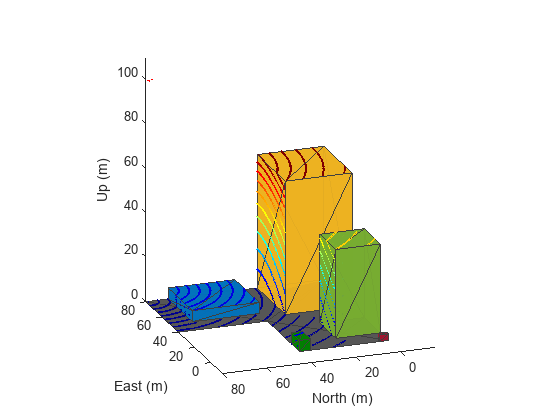
Simulate Mapping Flight and Map Building
[ax,plotFrames] = show3D(scene);
xlim([-15 80]);
ylim([-15 80]);
zlim([0 80]);
view([-115 20]);
axis equal
hold on

colormap('jet');
ptc = pointCloud(nan(1,1,3));
scatterplot = scatter3(nan,nan,nan,1,[0.3020 0.7451 0.9333], ...
    "Parent",plotFrames.UAV.Lidar);
scatterplot.XDataSource = "reshape(ptc.Location(:,:,1), [], 1)";
scatterplot.YDataSource = "reshape(ptc.Location(:,:,2), [], 1)";
scatterplot.ZDataSource = "reshape(ptc.Location(:,:,3), [], 1)";
scatterplot.CDataSource = "reshape(ptc.Location(:,:,3), [], 1) - min(reshape(ptc.Location(:,:,3), [], 1))";
hold off;

lidarSampleTime = [];
pt = cell(1,((updateRate*simTime) +1));
ptOut = cell(1,((updateRate*simTime) +1));
Create an occupancy map for a more efficient way to store the point cloud data. Use a minimum resolution of 1 cell per meter.
map3D = occupancyMap3D(1);
Simulate the mapping flight in the scenario. Store lidar sensor readings for each simulation step in a cell array after removing invalid points. Insert point clouds into the map using the insertPointCloud function. Ensure that the pose vector accounts for sensor offset.
setup(scene);

ptIdx = 0;
while scene.IsRunning
    ptIdx = ptIdx + 1;
    % Read the simulated lidar data from the scenario
    [isUpdated,lidarSampleTime,pt{ptIdx}] = read(lidar);

    if isUpdated
        % Get Lidar sensor's pose relative to ENU reference frame.
        sensorPose = getTransform(scene.TransformTree, "ENU","UAV/Lidar",lidarSampleTime);
        % Process the simulated Lidar pointcloud.
        ptc = pt{ptIdx};
        ptOut{ptIdx} = removeInvalidPoints(pt{ptIdx});
        % Construct the occupancy map using Lidar readings.
        insertPointCloud(map3D,[sensorPose(1:3,4)' tform2quat(sensorPose)],ptOut{ptIdx},500);

        figure(1)
        show3D(scene,"Time",lidarSampleTime,"FastUpdate",true,"Parent",ax);
        xlim([-15 80]);
        ylim([-15 80]);
        zlim([0 110]);
        view([-110 20]);

        refreshdata
        drawnow limitrate
    end

    % Show map building real time
    figure(2)
    show(map3D);
    view([-115 20]);
    axis equal

    advance(scene);
    updateSensors(scene);

end
![Figure contains an axes object. The axes object with title Occupancy Map, xlabel X [meters], ylabel Y [meters] contains an object of type patch.](../../examples/uav/win64/MapEnvironmentForMotionPlanningUsingUAVLidarExample_03.png)
Perform Motion Planning
Use insertPointCloud to assign probability an observational value of 0.4 for unoccupied cells and 0.7 for occupied cells. Specify the same as the thresholds for the occupancy map.
map3D.FreeThreshold = 0.4;
map3D.OccupiedThreshold = 0.7;
Use stateSpaceSE3 as the state space object for validator as the state vector of the state space is same as the pose vector.
ss = stateSpaceSE3([0 80;0 40;0 120;inf inf;inf inf;inf inf;inf inf]);
sv = validatorOccupancyMap3D(ss);
sv.Map = map3D;
sv.ValidationDistance = 0.1;
Use an optimal planner, RRT* is for planning. Planning continues even after goal is reached and terminates only when iteration limit is reached.
planner = plannerRRTStar(ss,sv);
planner.MaxConnectionDistance = 20;
planner.ContinueAfterGoalReached = true;
planner.MaxIterations = 500;
Specify a custom goal function that determines that a path reaches the goal if the Euclidean distance to the target is below a threshold of 1 meter.
planner.GoalReachedFcn = @(~,x,y)(norm(x(1:3)-y(1:3))<1);
planner.GoalBias = 0.1;
Specify start and goal poses and plan the path.
start = [3 5 5 1 0 0 0];
goal = [60 10 65 1 0 0 0];

rng(1,"twister"); % For repeatable results
[pthObj,solnInfo] = plan(planner,start,goal);
View Planned Path
close all
close all hidden

show(map3D)
axis equal
view([-115 20])
hold on
scatter3(start(1,1),start(1,2),start(1,3),'g','filled')                             % draw start state
scatter3(goal(1,1),goal(1,2),goal(1,3),'r','filled')                                % draw goal state
plot3(pthObj.States(:,1),pthObj.States(:,2),pthObj.States(:,3),'r-','LineWidth',2)  % draw path
![Figure contains an axes object. The axes object with title Occupancy Map, xlabel X [meters], ylabel Y [meters] contains 4 objects of type patch, scatter, line.](../../examples/uav/win64/MapEnvironmentForMotionPlanningUsingUAVLidarExample_04.png)
See Also
Objects
waypointTrajectory|uavLidarPointCloudGenerator|uavScenario|uavPlatform|plannerRRTStar(Navigation Toolbox)
Functions
insertPointCloud(Navigation Toolbox)