uavScenario
R2026bGenerate UAV simulation scenario
Description
The uavScenario object generates a UAV simulation scenario. To
add static meshes that represent buildings, terrain, and other obstacles to the scene, use the
addMesh object
function. To add a UAV platform to the scene, use the uavPlatform object. To
attach a sensor to the UAV platform, use the uavSensor
object.
Creation
Description
scene = uavScenario creates an empty UAV scenario with default
property values.
scene = uavScenario( sets
writable properties using one or more name-value arguments. For example,
Name=Value)uavScenario(StopTime=20) generates a UAV scenario that stops
simulating after 20 seconds.
Name-Value Arguments
Specify optional pairs of arguments as
Name1=Value1,...,NameN=ValueN, where Name is
the argument name and Value is the corresponding value.
Name-value arguments must appear after other arguments, but the order of the
pairs does not matter.
Scenario update rate, specified as a positive scalar in Hz.
The advance
object function advances the scenario by one time step, with a step size equal to
the inverse of the update rate.
This argument specifies the UpdateRate
property.
Data Types: double
Scenario stop time, specified as a nonnegative scalar in seconds. A scenario
stops advancing when the scenario time reaches the stop time or when the scenario
contains the maximum number of stored UAV platform poses specified by
HistoryBufferSize, whichever comes first.
This argument specifies the StopTime
property.
Data Types: double
Maximum number of stored UAV platform poses, specified as an integer greater than 1.
At each time step, the scenario stores the UAV platform poses. Once it contains the maximum number of stored UAV platform poses, the scenario stops storing additional UAV poses.
This argument specifies the HistoryBufferSize property.
Data Types: double
Scenario origin in geodetic coordinates, specified as a vector of the form [latitude longitude altitude]. The values of latitude and longitude specify the geodetic location of the origin in degrees, and altitude specifies the height of the origin above the WGS84 reference ellipsoid in meters.
This argument specifies the ReferenceLocation property.
Data Types: double
Maximum number of frames in the scenario, specified as a positive integer. The combined number of inertial, UAV platform, and sensor frames in the scenario must be less than or equal to the maximum number of frames.
This argument specifies the MaxNumFrames property.
Data Types: double
Properties
This property is read-only after object creation.
Scenario update rate, represented as a positive scalar in Hz.
Data Types: double
This property is read-only after object creation.
Scenario stop time, represented as a nonnegative scalar in seconds.
Data Types: double
This property is read-only after object creation.
Maximum number of stored UAV platform poses, represented as an integer greater than 1.
Data Types: double
This property is read-only after object creation.
Scenario origin in geodetic coordinates, represented as a vector of the form [latitude longitude altitude]. latitude and longitude are in degrees, and altitude is in meters.
Data Types: double
This property is read-only after object creation.
Maximum number of frames in the scenario, represented as a positive integer.
Data Types: double
This property is read-only.
Current scenario time, represented as a nonnegative scalar in seconds.
Data Types: double
This property is read-only.
Scenario activity state, represented as a logical 1
(true) or 0 (false). A value
of true indicates that the scenario is running, has not yet reached
the scenario stop time, and has not yet reached the maximum number of stored UAV
platform poses specified by HistoryBufferSize. A value of
false indicates that the scenario is not running.
Data Types: logical
This property is read-only.
Scenario frames transformation tree, represented as a transformTree
object. The transform tree contains the transformation information between the inertial,
platform, and sensor frames in the scenario. Use the getTransform
function of the transformTree
object to query transformations between frames.
This property is read-only.
Names of the inertial frames in the scenario, represented as a vector of strings.
By default, the inertial frame names are "ENU" and
"NED", which correspond to inertial frames with the east-north-up
and north-east-down orientations, respectively. To add a new inertial frame to the
scenario, use the addInertialFrame function.
Data Types: string
This property is read-only.
UAV platforms in the scenario, represented as an array of
uavPlatform objects. To add a UAV platform to the scenario, create
a uavPlatform
object.
This property is read-only.
Static meshes in the scenario, represented as a cell array of extendedObjectMesh
objects.
Each extendedObjectMesh represents a static mesh in the scenario.
To add a mesh to the UAV scenario, use the addMesh
function.
Object Functions
addMesh | Add new static mesh to UAV scenario |
addInertialFrame | Define new inertial frame in UAV scenario |
copy | Copy UAV scenario |
setup | Prepare UAV scenario for simulation |
advance | Advance UAV scenario simulation by one time step |
updateSensors | Update sensor readings in UAV scenario |
restart | Reset simulation of UAV scenario |
terrainHeight | Returns terrain height in UAV scenarios |
targetPoses | Find positions, orientations, velocities, angular velocities, and accelerations of targets relative to ego UAV platform |
Examples
Create a UAV scenario, and specify the update rate, stop time, and reference location. The reference location sets the geodetic origin of the scenario in latitude, longitude, and altitude.
scene = uavScenario(UpdateRate=200,StopTime=2,ReferenceLocation=[46, 42, 0]);
Add a custom inertial frame named MAP to the scenario. The MAP frame is offset 1 meter east from the default ENU (east-north-up) frame. Custom inertial frames enable you to define local coordinate systems for specific regions or tasks within the scenario.
addInertialFrame(scene,"ENU","MAP",trvec2tform([1 0 0]));
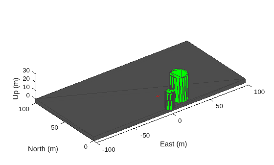
Add one ground mesh and two cylindrical obstacle meshes to the scenario. The polygon mesh represents the ground surface. The first cylinder is specified using Cartesian coordinates relative to the scenario origin. The second cylinder uses geographic coordinates (latitude, longitude, and radius) by setting UseLatLon to true, which is useful when you want to place obstacles at known geodetic positions.
addMesh(scene,"Polygon",{[-100 0; 100 0; 100 100; -100 100],[-5 0]},[0.3 0.3 0.3]); addMesh(scene,"Cylinder",{[20 10 10],[0 30]},[0 1 0]); addMesh(scene,"Cylinder",{[46 42 5],[0 20]},[0 1 0],UseLatLon=true);
Add a UAV platform with a specified waypoint trajectory to the scenario. The trajectory defines a flight path through three waypoints with arrival times at 0, 1, and 2 seconds.
traj = waypointTrajectory(Waypoints=[0 -20 -5; 20 -20 -5; 20 0 -5],TimeOfArrival=[0 1 2]);
uavPlat = uavPlatform("UAV",scene,Trajectory=traj);Add meshes to the UAV platform for visualization. The first mesh is a quadrotor body with a wingspan of 4 meters displayed in red. Then, add a geofence boundary to constrain the UAV flight region.
updateMesh(uavPlat,"quadrotor",{4},[1 0 0],eul2tform([0 0 pi])); addGeoFence(uavPlat,"Polygon",{[-50 0;50 0;50 50;-50 50],[0 100]},true,ReferenceFrame="ENU");
Attach an inertial navigation system (INS) sensor to the UAV platform. The INS sensor provides position, velocity, and orientation measurements during simulation.
insModel = insSensor;
ins = uavSensor("INS",uavPlat,insModel,MountingLocation=[4 0 0]); Visualize the scenario in 3D.
ax = show3D(scene);
axis(ax,"equal"); Set up and start the scenario.
% Set up scenario setup(scene); % Start scenario while advance(scene) % Update sensor readings updateSensors(scene); % Visualize the scenario show3D(scene,"Parent",ax,"FastUpdate",true); drawnow limitrate end
Add Terrain Mesh to UAV Scenario
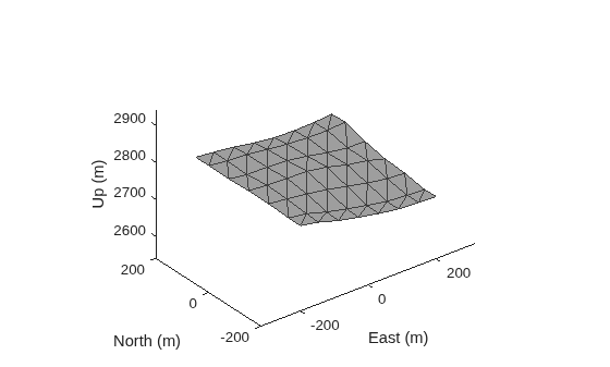
Create a UAV scenario with a specified reference location.
scenario = uavScenario(ReferenceLocation=[39.5 -105.5 0]);
Add custom terrain data from the n39_w106_3arc_v2.dt1 DTED file.
addCustomTerrain("CustomTerrain","n39_w106_3arc_v2.dt1");
Add the terrain mesh to the UAV scenario.
addMesh(scenario,"terrain",{"CustomTerrain",[-200 200],[-200 200]},[0.6 0.6 0.6]);
Show the UAV scenario.
show3D(scenario);
Add Building Mesh to UAV Scenario
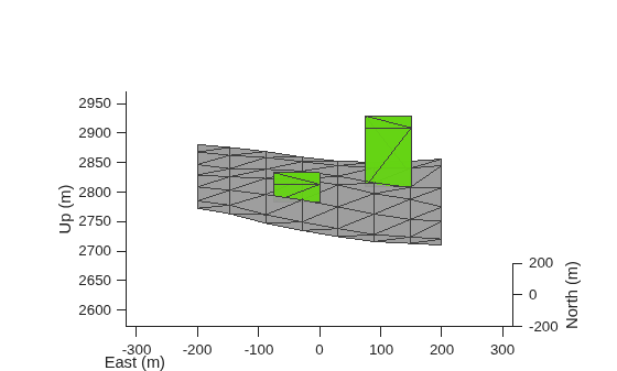
Specify the building mesh centers, heights, and boundaries.
Tip: Use the terrainHeight function to obtain the ground height at specific locations, as shown in the loop below for each building base.
buildingCenters = [-50 -50;100 100]; buildingHeights = [30 100]; buildingBoundary = [-25 -25; -25 50; 50 50; 50 -25];
Add the building mesh to the UAV scenario.
for idx = 1:size(buildingCenters,1) buildingVertices = buildingBoundary+buildingCenters(idx,:); buildingBase = min(terrainHeight(scenario,buildingVertices(:,1),buildingVertices(:,2))); addMesh(scenario,"polygon",{buildingVertices,buildingBase+[0 buildingHeights(idx)]},[0.3922 0.8314 0.0745]); end
Show the UAV scenario.
show3D(scenario); view([0 15])
Version History
Introduced in R2020b
MATLAB Command
You clicked a link that corresponds to this MATLAB command:
Run the command by entering it in the MATLAB Command Window. Web browsers do not support MATLAB commands.
Select a Web Site
Choose a web site to get translated content where available and see local events and offers. Based on your location, we recommend that you select: .
You can also select a web site from the following list
How to Get Best Site Performance
Select the China site (in Chinese or English) for best site performance. Other MathWorks country sites are not optimized for visits from your location.
Americas
- América Latina (Español)
- Canada (English)
- United States (English)
Europe
- Belgium (English)
- Denmark (English)
- Deutschland (Deutsch)
- España (Español)
- Finland (English)
- France (Français)
- Ireland (English)
- Italia (Italiano)
- Luxembourg (English)
- Netherlands (English)
- Norway (English)
- Österreich (Deutsch)
- Portugal (English)
- Sweden (English)
- Switzerland
- United Kingdom (English)