Data Converters
Simulate and analyze performance metrics of analog-to-digital and digital-to-analog data converters. Start from complete system-level models of typical ADC or DAC architectures. Modify ADC or DAC parameters until you reach your desired system specifications. Use Measurements and Testbenches to validate your design.
Blocks
Topics
- ADC Tutorial
This tutorial example shows you how to design a second order Delta Sigma Analog to Digital Converter in Simulink®.
- STEP 1: System-Level Model of DSM ADC
- STEP 2: SystemVerilog Module Generation
- STEP 3: Final System-Level Model
- Compare SAR ADC to Ideal ADC
This example shows a comparison of the SAR ADC from the Mixed-Signal Blockset™ to the ideal ADC model with impairments presented in Analyzing Simple ADC with Impairments.
- Design and Evaluate SAR ADC
This example shows how to design a SAR ADC using reference architecture and validate the ADC using ADC Testbench.
- Design and Evaluate Interleaved ADC Using System Object
This example shows how to use System objects to model and evaluate the performance of an interleaved ADC.
- Effect of Metastability Impairment in Flash ADC
This example shows how to customize a flash Analog to Digital Converter (ADC) by adding the metastability probability as an impairment.
- Compare Binary Weighted DAC to Ideal DAC
This example shows a comparison of the Binary Weighted DAC from the Mixed-Signal Blockset™ to an ideal DAC model.
- Delta Sigma Modulator Data Converter with Half-Band Filter for Decimation
Use the delta sigma modulator data converter for an analog-to-digital converter application.
- Model Continuous-Time Delta Sigma Modulator With Inherent Anti-Aliasing Property
This example shows how to design a continuous-time delta sigma modulator (CT DSM) using the DT-CT Translation method explained in [1].
Featured Examples

Model MASH and SMASH Delta Sigma Modulators
Model multi-stage noise-shaping (MASH) or cascade Delta Sigma Modulators (DSM) using the Delta-Sigma Modulator block. MASH structures work by feeding the quantization error from the present stage to the next stage and combining the outputs from multiple stages in a digital cancellation logic. The advantage of cascade DSMs is that you can get the performance of higher order DSM without their stability issues.

Model Continuous-Time Band-Pass Delta-Sigma Modulator
Different ways of implementing a continuous-time (CT) band-pass delta-sigma modulator (BP-DSM) based on multi-path feedback loop or using a Finite Impulse Response (FIR) filter in the feedback path.
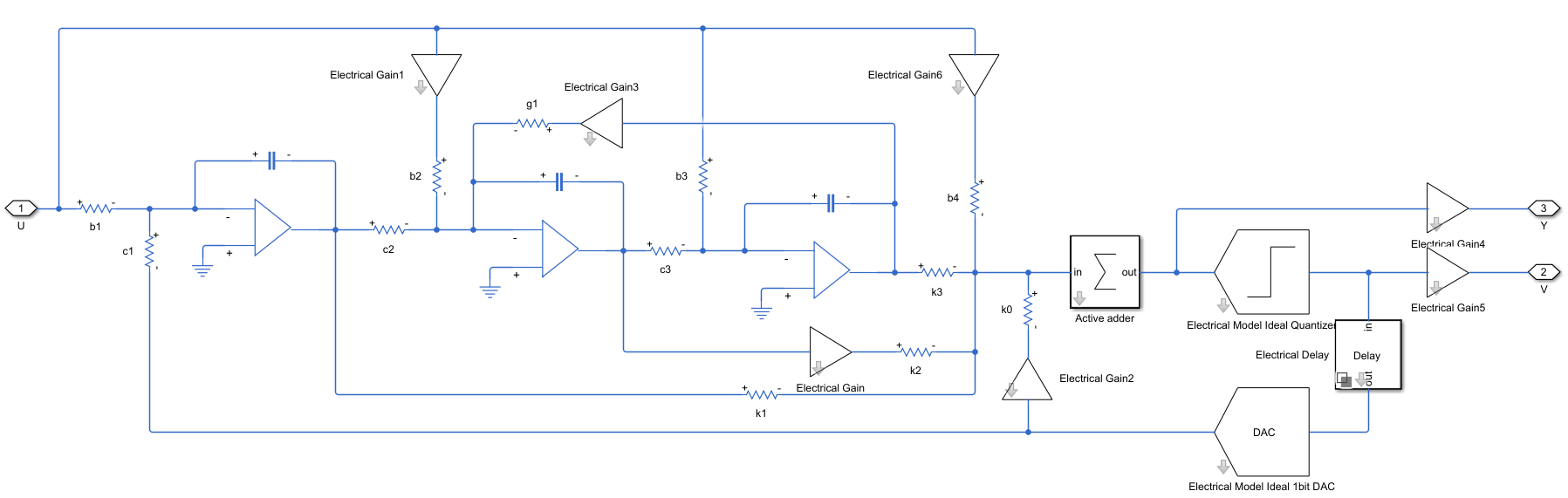
Model Continuous-Time Low-Pass Delta-Sigma Modulator with Different Levels of Abstraction
Synthesize, model and simulate a 3rd-order continuous-time (CT) low pass Delta-Sigma Modulator (LP-DSM), by using various levels of abstraction, starting from ideal/system-level model using Mixed-Signal Blockset's DSM block to a schematic model based on Simscape blocks.

Analyzing Simple ADC with Impairments
Implement a basic ADC using a Zero-Order Hold block as a sampler. This simple ADC highlights some of the typical impairments introduced in an analog-to-digital converters such as aperture jitter, nonlinearity, quantization, and saturation. This example shows how to measure the effects of such impairments using a Spectrum Analyzer block and the ADC AC Measurement block from the Mixed-Signal Blockset™. To better approximate real-world performance, you can individually enable the impairments in the model.

Design and Evaluate Successive Approximation ADC Using Stateflow
Design and evaluate a 12-bit successive approximation register ADC.

Subranging ADC
Model a 6-bit Subranging ADC with pipelining and an error correcting second stage.

Design and Evaluate Interleaved ADC
This interleaved ADC model highlights some of the typical impairments introduced by data converters and their effects on a larger system.

Oversampling Interpolating DAC
Model a 12-bit Oversampling Interpolating DAC.

Design and Evaluate Segmented DAC
Design and evaluate a segmented DAC using reference architecture and validate the DAC using the DAC Testbench. For this example, use the datasheet of AD9775. This is a commercial, off-the-shelf 14-bit DAC from Analog Devices.