Interleaved ADC
Libraries:
Mixed-Signal Blockset /
ADC /
Architectures
Description
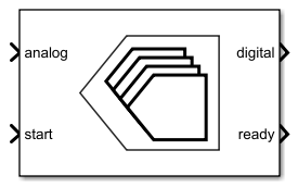
Use the Interleaved ADC to support the time-interleaved ADC models in your design. This block is compatible with the SerDes Toolbox™ IBIS-AMI models. You can use the block to model over an infinite input range and number of bits. This block uses Flash ADC as its core.
An interleaved ADC consists of a set of ADC cores wired in parallel.

At the rising edge of a signal at the start port, the ADC starts a conversion on the current core and indexes the input switch to the next core. When the conversion is complete, the output switch changes to the core in question. The conversion result is available at the digital port. The block also sends the rising edge of a signal on the ready port. This result is held until the next conversion is complete.
While a conversion is ongoing in one ADC core, the block can start new conversions in the other cores, increasing the throughput compared to a single core ADC.
Ports
Input
Analog input signal, specified as a scalar.
Data Types: double
External clock to start conversion, specified as a scalar or a vector. If specified as a vector, the number of elements in the vector must be equal to the number of ADC cores.
The analog to digital conversion process starts at the rising edge of the signal at the start port.
Data Types: double | Boolean
Add to the ADC input to calibrate the offset error, specified as a scalar or a vector. If specified as a scalar, it is demultiplexed over analog inputs of the ADC cores. If specified as a vector, the number of elements in the vector must be equal to the number of ADC cores. The vector elements are applied per ADC core.
You can also use the port to dynamically calibrate the offset error to each ADC core.
Data Types: double
Multiply the analog input to calibrate the gain error, specified as a scalar or a vector. If specified as a scalar, it is demultiplexed over analog inputs of the ADC cores. If specified as a vector, the number of elements in the vector must be equal to the number of ADC cores. The vector elements are applied per ADC core.
You can also use the port to dynamically calibrate the gain error to each ADC core.
Data Types: double
Output
Converted digital output signal, returned as a scalar.
Data Types: fixed point | single | double | int8 | int16 | int32 | uint8 | uint16 | uint32
Determines whether the analog to digital conversion is complete, returned as a scalar.
Usually, the data type of the ready signal is the same as the data type of the start signal. But if the start signal is a fixed-point type or a 64-bit integer type, the data type of the ready signal defaults to Boolean.
Data Types: double | Boolean
Parameters
Configuration
Number of physical output bits for all ADC cores, specified as a unitless positive real integer scalar or vector with length NADCs. Number of bits determines the resolution of the ADC.
Programmatic Use
Block parameter:
NBits |
| Type: character vector |
| Values: scalar | vector |
Default:
8 |
Data Types: double
ADC dynamic range, specified as a 2-element row vector in volts.
Programmatic Use
Block parameter:
InputRange |
| Type: character vector |
| Values: 2-element row vector | [NADCs x 2] matrix |
Default:
[-1 1] |
Data Types: double
Select to enable sub-sample interpolation with sinusoidal conversion start signal. This approximates the input value at the zero-crossing of the input clock.
For square conversion start signals, disable this parameter.
Number of ADC cores to interleave, specified as a positive real integer.
Programmatic Use
Block parameter:
NADCs |
| Type: character vector |
| Values: positive real integer |
Default:
4 |
Data Types: double
Inherit the output polarity and data type from the analog input signal to the ADC. If you select this option, the ADC ignores the Output polarity and Output data type parameters. The ADC output has the same polarity as the input and the data type is double.
Defines the ADC output data polarity.
If Output polarity is set to Auto,
the minimum and maximum values of the output are determined by the polarity of the
Input range.
If Output polarity is set to
Bipolar, the outputs are between
-2NBits-1 and
2NBits-1-1.
If Output polarity is set to
Unipolar, the outputs are between 0
and 2NBits-1.
Dependencies
To enable this parameter, deselect the Match output to input scale option.
Programmatic Use
Block parameter:
OutputPolarity |
| Type: character vector |
Values:
Auto | Bipolar |
Unipolar |
Default:
Auto |
Defines ADC output data type.
Dependencies
To enable this parameter, deselect the Match output to input scale option.
Programmatic Use
Block parameter:
OutDataType |
| Type: character vector |
Values:
double | single |
(u)int8 | (u)int16 |
(u)int32 |
fixdt(OutputPolarity,NBits) |
Default:
double |
Convert the output of the ADC to scalar. The block selects the most recent conversion result using an internal counter to produce the scalar output.
Fixed-step sample rate, specified as a positive real scalar. When using in SerDes systems, Sample time represents the IBIS-AMI sample interval.
Programmatic Use
Block parameter:
SampleTime |
| Type: character vector |
| Values: positive real scalar |
Default:
6.25e-12 |
Define how the Interleaved ADC block is used in the simulation. You can use the block as a Simulink® block, or use the System object™ implementation (either interpreted or code generation) for more control.
Impairments
Select to enable linearity impairments such as offset error and gain error in ADC simulation. By default, this option is deselected.
Shifts quantization steps by specific value, specified as a scalar in %FS, FS, or LSB.
Note
The full scale range of the converter is defined as the difference between the last and first code on the +0.5 LSB compensated transfer curve. In a +0.5 LSB compensated transfer curve, first code is 0.5 LSB wide while the last code is 1.5 LSB wide. The input values must be considered within the full scale range of the converter.
Note
LSB is calculated by the equation .
Dependencies
To enable this parameter, select Enable linearity impairments in the Impairments tab.
Programmatic Use
Block parameter:
OffsetError |
| Type: character vector |
| Values: real scalar |
Default:
0 LSB |
Data Types: double
Error on the slope of the straight line that interpolates the ADC transfer curve, specified as a real scalar in %FS, FS, or LSB.
Note
The full scale range of the converter is defined as the difference between the last and first code on the +0.5 LSB compensated transfer curve. In a +0.5 LSB compensated transfer curve, first code is 0.5 LSB wide while the last code is 1.5 LSB wide. The input values must be considered within the full scale range of the converter.
Note
LSB is calculated by the equation .
Dependencies
To enable this parameter, select Enable linearity impairments in the Impairments tab.
Programmatic Use
Block parameter:
GainError |
| Type: character vector |
| Values: real scalar |
Default:
0 LSB |
Data Types: double
Select to enable timing impairments such as conversion delay in ADC simulation. By default, this option is deselected.
Latency of the analog to digital converter, specified as a nonnegative real scalar. If specified as a fraction, the Interleaved ADC block rounds it to the closest integer multiple of the sample time.
Dependencies
This parameter is only available when Enable timing impairments is selected. If you are using the Flash ADC in the System object mode, this value is rounded to the nearest multiple of the sample interval.
Programmatic Use
Block parameter:
ConversionDelay |
| Type: character vector |
| Values: real scalar |
Default:
0 |
Data Types: double
Select to enable the offset calibration port. The value at this port is added to the analog input to calibrate the offset error after gain error calibration is complete.
Select to enable the gain calibration port. The value at this port is multiplied by the analog input to calibrate the gain error.
Version History
Introduced in R2023b
MATLAB Command
You clicked a link that corresponds to this MATLAB command:
Run the command by entering it in the MATLAB Command Window. Web browsers do not support MATLAB commands.
Select a Web Site
Choose a web site to get translated content where available and see local events and offers. Based on your location, we recommend that you select: .
You can also select a web site from the following list
How to Get Best Site Performance
Select the China site (in Chinese or English) for best site performance. Other MathWorks country sites are not optimized for visits from your location.
Americas
- América Latina (Español)
- Canada (English)
- United States (English)
Europe
- Belgium (English)
- Denmark (English)
- Deutschland (Deutsch)
- España (Español)
- Finland (English)
- France (Français)
- Ireland (English)
- Italia (Italiano)
- Luxembourg (English)
- Netherlands (English)
- Norway (English)
- Österreich (Deutsch)
- Portugal (English)
- Sweden (English)
- Switzerland
- United Kingdom (English)