Channelizer
Polyphase filter bank and fast Fourier transform
Libraries:
DSP HDL Toolbox /
Filtering
Description
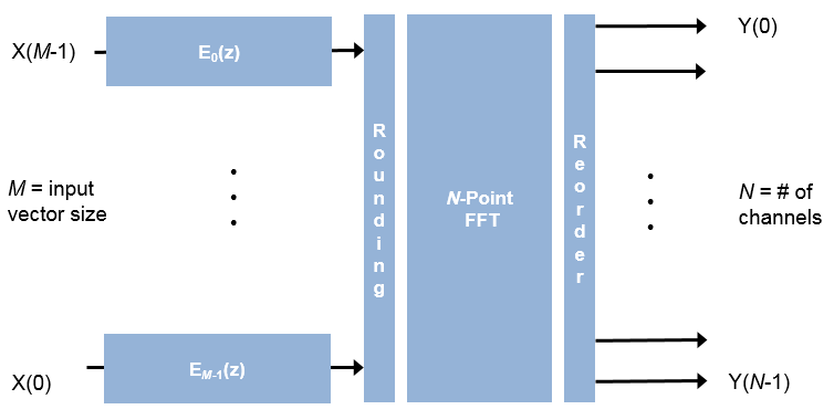
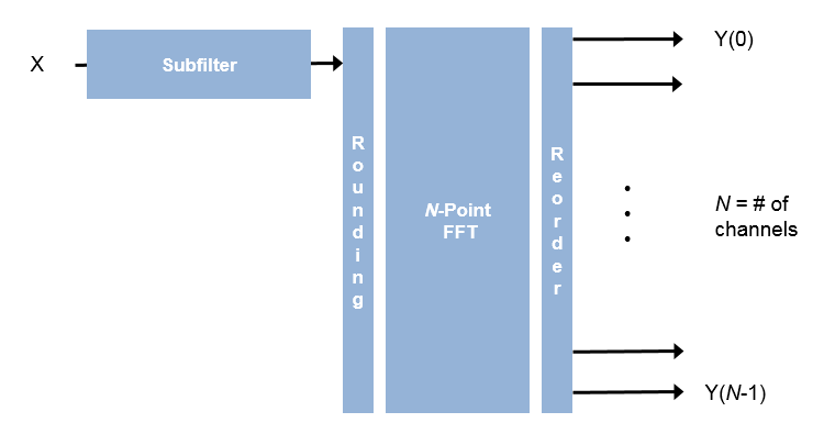
The Channelizer block separates a broadband input signal into multiple narrowband output signals. It provides hardware speed and area optimization for streaming data applications. The block accepts scalar or vector input of real or complex data, provides hardware-friendly control signals, and has optional output frame control signals. You can achieve gigasamples-per-second (GSPS) throughput, also called super sample rates, using vector input. The block implements a polyphase filter, with one subfilter per input vector element. The hardware implementation interleaves the subfilters, which results in sharing each filter multiplier (FFT Length / Input Size) times. The FFT implementation uses the same pipelined Radix 2^2 FFT algorithm as the FFT block.
Note
The output of this block has a phase shift compared to the Channelizer (DSP System Toolbox™) block, unless you select the Preserve channel phase check box. The channels detected by both blocks match when analyzed over multiple frames. Also, to match the Channelizer (DSP System Toolbox) block, apply FFT Length – 1 zeros at the start of the data stream. For an example of comparing the two algorithms, see Preserve Channelizer Phase.
Note
You can also generate HDL code for this hardware-optimized algorithm, without creating a Simulink® model, by using the DSP HDL IP Designer app. The app provides the same interface and configuration options as the Simulink block.
Examples

High-Throughput Channelizer for FPGA
Implement a polyphase filter bank channelizer with throughput of gigasamples-per-second (GSPS).

HDL Implementation of Four Channel Synthesizer and Channelizer
Synthesize four stereo signals into a broadband signal and split the signal back into the individual narrowband signals.
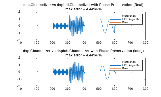
Preserve Channelizer Phase
Separate channels of a sine wave signal with multiple frequencies, and compare the results using dsp.Channelizer and dsphdl.Channelizer objects.
Ports
Input
Output
Parameters
Algorithms
The polyphase filter algorithm implements a subfilter for each FFT channel. For more detail on the polyphase filter architecture, refer to [1], and to the Channelizer (DSP System Toolbox) block reference page.
If the input vector size, M, is the same as the FFT length,
N, then the block implements N subfilters in
the hardware. Each subfilter is an FIR filter (Direct form
transposed or Direct form systolic) with
NumCoeffs/N taps.
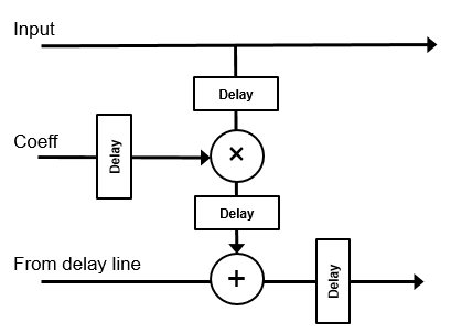
If the vector size is less than N, the block implements one subfilter for each input vector element. The subfilter multipliers are shared as necessary to implement N channel filters. The shared multiplier taps have a lookup table for N/M filter coefficients. Each tap is followed by a delay line of N/M–1 cycles.

The block casts the output of the subfilters to the specified Filter output data type by using the rounding and overflow settings you select. Each filter tap in the subfilter is pipelined to target the DSP sections of an FPGA.
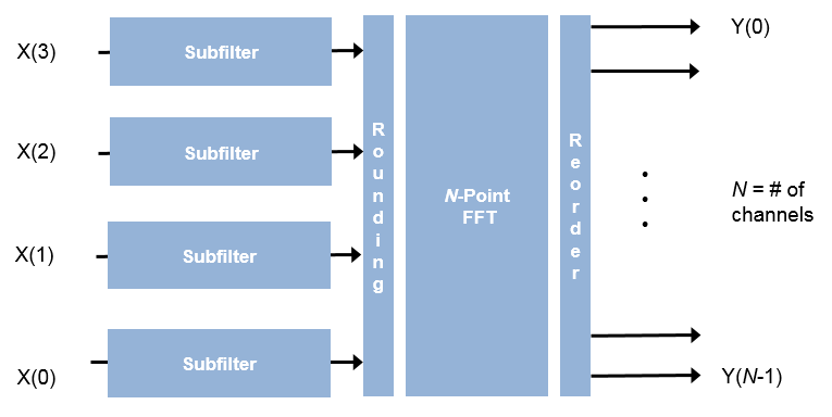
For instance, for an FFT length of 8, and an input vector size of 4, the block implements four filters. Each multiplier is shared N/M times, or twice. Each tap applies two coefficients, and the delay line is N/M–1 cycles.
For scalar input, the block implements one filter. Each multiplier is shared N times. Each tap applies N coefficients, and the delay line is N–1 cycles.
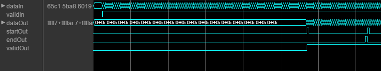
This diagram shows validIn and validOut signals for
contiguous input data with a vector size of 16, an FFT length of 512, and when you
select the Direct form transposed filter architecture. In this
example, the output vector size is specified same as the input vector size.
The diagram also shows the optional startOut and endOut
signals that indicate frame boundaries. When enabled, startOut pulses for
one cycle with the first validOut of the frame, and
endOut pulses for one cycle with the last validOut
of the frame.
If you apply continuous input frames (no gap in validIn between frames),
the output will also be continuous, after the initial latency.
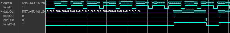
The validIn signal can be noncontiguous. Data accompanied by a
validIn signal is stored until a frame is filled. Then
the data in output is a contiguous frame of
N/M cycles. This diagram shows
noncontiguous input and contiguous output for an FFT length of 512 and a vector size
of 16 samples.
References
[1] Harris, F. J., C. Dick, and M. Rice. “Digital Receivers and Transmitters Using Polyphase Filter Banks for Wireless Communications.” IEEE Transactions on Microwave Theory and Techniques. Vol. 51, No. 4, April 2003.