Model Global Data by Creating Data Stores
A data store is a repository to which you can write data, and from which you can read data, without having to connect an input or output signal directly to the data store. Data stores are accessible across model levels, so subsystems and referenced models can use data stores to share data without using I/O ports. To decide whether to use data stores, see Data Store Basics.
Data Store Examples
Overview
The following examples illustrate techniques for defining and accessing data stores. See Order Data Store Access for techniques that control data store access over time, such as ensuring that a given data store is always written before it is read. See Data Store Diagnostics for techniques you can use to help detect and correct potential data store errors without needing to run any simulations.
Note
To use global data stores to share data among referenced models, see Use Data Stores Across Multiple Models.
Local Data Store Example
The following model illustrates creation and access of a local data store, which is visible only in a model or particular subsystem.
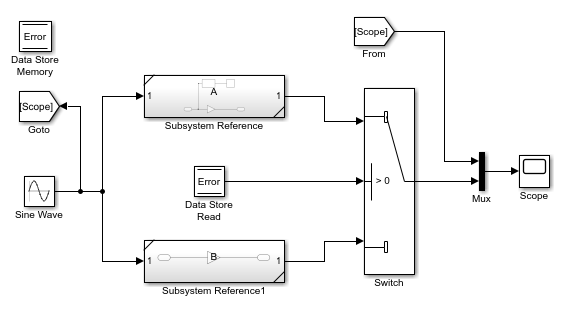
This model uses a data store to permit subsystem A to signal that its output is invalid.
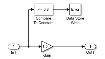
If subsystem A's output is invalid, the model uses the output of subsystem B.

Global Data Store Example
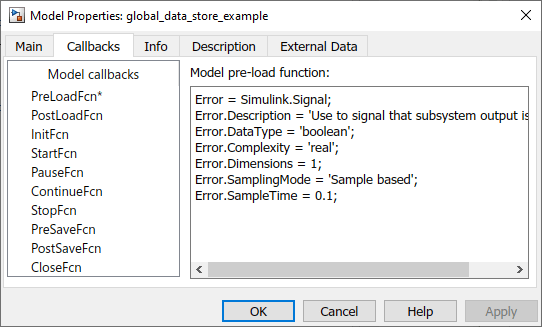
The following model replaces the subsystems of the previous example with functionally identical referenced models to illustrate use of a global data store to share data in a model reference hierarchy.

In this example, the top model uses a signal object in the MATLAB® workspace to define the error data store. This is necessary
because data stores are visible across model boundaries only if they are defined
by signal objects in the MATLAB workspace or a data dictionary. The model specifies code for the
PreLoadFcn model callback parameter that creates the
signal object. This code executes before the model loads.
Create and Apply Data Stores
Note
To use buses and arrays of buses with data stores, perform both the following procedure and Setting Up a Model to Use Data Stores with Buses and Arrays of Buses.
The following is a general workflow for configuring data stores. You can perform the tasks in a different order, or separately from the rest, depending on how you use data stores.
Where applicable, plan your use of data stores to minimize their effect on software verification. For more information, see Data Stores and Software Verification.
Create data stores using the techniques described in Data Stores with Data Store Memory Blocks or Data Stores with Signal Objects. For greater reliability, consider assigning rather than inheriting data store attributes, as described in Specifying Data Store Memory Block Attributes.
Add to the model Data Store Write and Data Store Read blocks to write to and read from the data stores, as described in Access Data Stores with Simulink Blocks.
Configure the model and the blocks that access each data store to avoid concurrency failures when reading and writing the data store, as described in Order Data Store Access.
Apply the techniques described in Data Store Diagnostics as needed to prevent data store errors, or to diagnose them if they occur during simulation.
If you intend to generate code for your model, see Data Stores in Generated Code (Simulink Coder).
To create a data store, you create a Data Store Memory block or a
Simulink.Signal object. The block
or signal object represents the data store and specifies its properties. Every data
store must have a unique name.
A Data Store Memory block implements a local data store. See Data Stores with Data Store Memory Blocks.
A
Simulink.Signalobject can act as a local or global data store. See Data Stores with Signal Objects.
Data stores implemented with Data Store Memory blocks:
Support data store initialization
Provide control of data store scope and options at specific levels in the model hierarchy
Require a block to represent the data store
Cannot be accessed within referenced models
Cannot be in a subsystem that a For Each Subsystem block represents.
Data stores implemented with Simulink.Signal objects:
Provide model-wide control of data store scope and options
Do not require a block to represent the data store
Can be accessed in referenced models, if the data store is global
Be careful not to equate local data stores with Data Store Memory blocks, and
global data stores with Simulink.Signal objects. Either
technique can define a local data store, and a signal object can define either a
local or a global data store.
Data Stores with Data Store Memory Blocks
Creating the Data Store
To use a Data Store Memory block to define a data store, drag an instance of the block into the model at the topmost level from which you want the data store to be visible. The result is a local data store, which is not accessible within referenced models.
To define a data store that is visible at every level within a given model, except within Model blocks, drag the Data Store Memory block into the root level of the model.
To define a data store that is visible only within a particular subsystem and the subsystems that it contains, but not within Model blocks, drag the Data Store Memory block into the subsystem.
Once you have added the Data Store Memory block, use its parameters to define the data store's properties. The Data store name property specifies the name of the data store that the Data Store Write and Data Store Read blocks access. See Data Store Memory documentation for details.
You can specify data store properties beyond those definable with Data Store Memory block parameters by selecting the Data store name must resolve to Simulink signal object option and using a signal object as the data store name. See Specifying Attributes Using a Signal Object for details.
Specifying Data Store Memory Block Attributes
A Data Store Memory block can inherit three data attributes from its corresponding Data Store Read and Data Store Write blocks. The inheritable attributes are:
Data type
Complexity
Sample time
However, allowing these attributes to be inherited can cause unexpected
results that can be difficult to debug. To prevent such errors, use the Data
Store Memory block dialog or a Simulink.Signal object to
specify the attributes explicitly.
Specifying Attributes Using Block Parameters
You can use the Data Store Memory block dialog box or the Model Data
Editor Data Stores tab (in the
Modeling tab, click Model Data
Editor) to specify the data type and complexity of a data
store. In the next figure, the block dialog box sets the Data
type to uint16 and the Signal
type to real.

Specifying Attributes Using a Signal Object
You can use a Simulink.Signal object to specify data
store attributes for a Data Store Memory block.
Tip
To establish an implicit data store, as described in Data Stores with Signal Objects, use the same general approach as when you explicitly associate a signal object with a Data Store Memory block.
The next figure shows a Data Store Memory block that specifies resolution
to a Simulink.Signal object, named A. To
use a signal object for the data store, set Data store
name to the name of the signal object. For compile-time
checking, open the Signal Attributes tab and select the
Data store name must resolve to Simulink signal
object parameter.

Alternatively, on the Model Data Editor Data Stores
tab (on the Modeling tab, click Model Data
Editor), while editing the data store name, click the nearby
action button ![]() and select Create and
Resolve. In the Create New Data dialog box, set
Value to
and select Create and
Resolve. In the Create New Data dialog box, set
Value to Simulink.Signal.
The signal object specifies values for all three data attributes that the
data store would otherwise inherit. In this example, which defines a local
data store, the Simulink.Signal object A
has the following inherited properties: DataType,
Complexity, and SampleTime.
A =

Simulink.Signal (handle)
         CoderInfo: [1x1 Simulink.CoderInfo]
       Description: ''
          DataType: 'auto'
               Min: []
               Max: []
              Unit: ''
        Dimensions: 1
    DimensionsMode: 'auto'
        Complexity: 'auto'
        SampleTime: -1
      InitialValue: 0
For more information about specifying signal object attributes for local and global data stores, see Signal Object Attributes for Data Stores.
Use Model Data Editor to Configure Data Store Memory Blocks in a List. Use the Data Stores tab in the Model Data Editor to configure the parameters of a Data Store Memory block. Use this technique to configure the data store without locating it in the model and to configure the data store together with other interface elements such as Inport and Outport blocks. The Model Data Editor also shows you information for Data Store Read and Data Store Write blocks in the same list.
To open the Model Data Editor, in the Modeling tab, click Model Data Editor.
Data Stores with Signal Objects
Creating the Data Store
To use a Simulink.Signal object to define a data store
without using a Data Store Memory block, create the signal object in a workspace
that is visible to every component that needs to access the data store. The name
of the associated data store is the name of the signal object. You can use this
name in Data Store Read and Data Store Write blocks, just as if it were the
Data store name of a Data Store Memory
block. Simulink® creates an associated data store when you use the signal object
for data storage.
Local and Global Data Stores
You can use a Simulink.Signal object to define either a local
or a global data store.
If you define the object in the MATLAB base workspace or a data dictionary, the result is a global data store, which is accessible in every model within Simulink, including all referenced models.
If you create the object in a model workspace, the result is a local data store, which is accessible at every level in a model except any referenced models.
Signal Object Attributes for Data Stores
Those data store attributes that a signal object does not define have the same default values that they do in a Data Store Memory block. The property values of a signal object used as a data store have different requirements, depending on whether the data store is local or global.
Once you have created the object, set the properties of the signal object to
the values that you want the corresponding data store properties to have. For
example, the following commands define a data store named
Error in the MATLAB base workspace:
Error = Simulink.Signal;
Error.Description = 'Use to signal that subsystem output is invalid';
Error.DataType = 'boolean';
Error.Complexity = 'real';
Error.Dimensions = 1;
Error.SampleTime = 0.1;
Attributes for Local Data Stores. For a local data store, for each parameter listed below, you can either set the value explicitly or you can have the data store inherit the value from the Data Store Write and Data Store Read blocks.
DataTypeComplexitySampleTime
To define a local data store using a Data Store Memory block, you can use a signal object for the Data store name parameter. For compile-time checking, in the Signal Attributes tab, select the Data store must resolve to Simulink signal object parameter. The Data store must resolve to Simulink signal object parameter causes Simulink to display an error and stop compilation if Simulink cannot find the signal object or if the signal object properties are inconsistent with the signal object properties.
Attributes for Global Data Stores. The following table describes the parameter requirements for global data stores.
| Parameter | Global Data Store Value |
|---|---|
DataType | Must be set explicitly |
Complexity | Must be set explicitly |
Dimensions | Can be set or inherited |
SampleTime | Can be set or inherited |
Modify Attributes of Data Store Defined by Signal Object. You can use the Model Data Editor (in the Modeling
tab, click Model Data Editor) to modify and inspect the
attributes of data stores, Data Store Read, and Data
Store Write blocks. On the Data Stores tab,
to show the attributes of data stores that you define by using signal
objects (such as Simulink.Signal), click the
Show/refresh additional information button. Then,
if a Data Store Read or Data Store Write block
shown in the data table refers to a data store defined by a signal object,
the table includes a row that corresponds to the object.
For more information, see Model Data Editor.
Access Data Stores with Simulink Blocks
Writing to a Data Store
To set the value of a data store at each time step:
Create an instance of a Data Store Write block at the level of your model that computes the value.
Set the Data Store Write block Data store name parameter to the name of the data store to which you want it to write data.
Connect the output of the block that computes the value to the input of the Data Store Write block.

Reading from a Data Store
To get the value of a data store at each time step:
Create an instance of a Data Store Read block at the level of your model that needs the value.
Set the Data Store Read block Data store name parameter to the name of the data store from which you want it to read.
Connect the output of the Data Store Read block to the input of the block that needs the data store value.

Accessing a Global Data Store
When connected to a global data store (one that is defined by a signal object
in the MATLAB workspace), a Data Store Read or Data Store Write block displays
the word global above the data store name.

Order Data Store Access
About Data Store Access Order
To obtain correct results from data stores, you must control the order of execution of the data store’s reads and writes. If a data store’s read occurs before its write, latency is introduced into the algorithm: the read obtains the value that was computed and stored in the previous time step, rather than the value computed and stored in the current time step.
Such latency may cause the system to behave other than as designed, and in some cases may destabilize the system. Even if these problems do not occur, an uncontrolled access order could change from one release of Simulink to the next.
This section describes several strategies for explicitly controlling the order of execution of a data store’s reads and writes. See Data Store Diagnostics for techniques you can use to detect and correct potential data store errors without running simulations.
Ordering Access Using Function Call Subsystems
You can use function call subsystems to control the execution order of model components that access data stores. The next figure shows this technique:


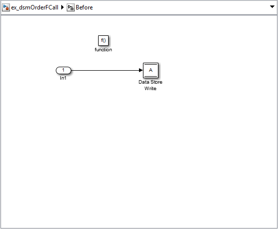

The subsystem Before contains the Data Store Write, and the
Stateflow® chart calls that subsystem before it calls the subsystem
After, which contains the Data Store Read.
Ordering Access Using Block Priorities
You can embed data store reads and writes inside atomic subsystems or Model blocks whose priorities specify their relative execution order. For more information about configuring priority in which Simulink blocks execute, see Set Priority in Execution Order of Blocks.
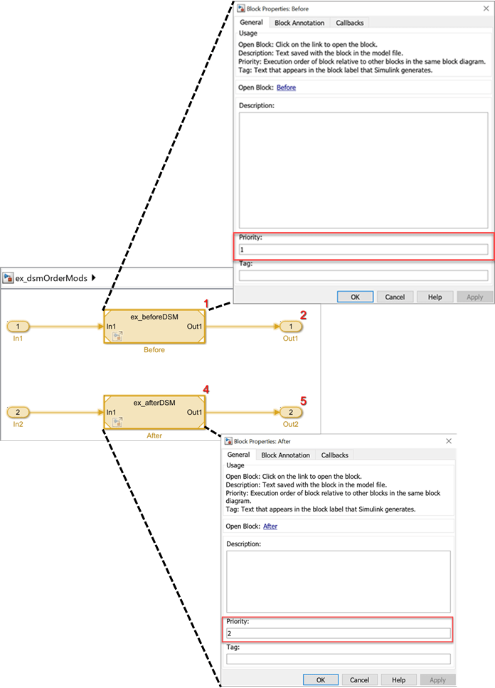
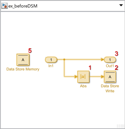

The Model block beforeDSM has a lower priority then
afterDSM, so it is guaranteed to execute first. Since
beforeDSM is atomic, all of its operations, including the
Data Store Write, will execute prior to afterDSM and all of
its operations, including the Data Store Read.
Data Stores with Buses and Arrays of Buses
Benefits of using data stores with buses and arrays of buses include:
Simplifying the model layout by associating multiple signals with a single data store
Producing generated code that represents the data in the store data as structures that reflect the bus hierarchy
Writing to and reading from data stores without creating data copies, which results in more efficient data access
You cannot use a bus or array of buses that contains:
Variable-dimension signals
Frame-based signals
Setting Up a Model to Use Data Stores with Buses and Arrays of Buses
This procedure applies to local and global data stores, and to data stores
defined with a Data Store Memory block or a Simulink.Signal
object. Before performing the procedure, you must understand how to use data
stores in a model, as described in Create and Apply Data Stores.
To use buses and arrays of buses with data stores:
Use the Type Editor to define a bus object whose properties match the bus data that you want to write to and read from a data store. For details, see Create Simulink Bus Objects.
Add a data store (using a Data Store Memory block or a
Simulink.Signalobject) for storing the bus data.Specify the bus object as the data type of the data store. For details, see Specify a Bus Object Data Type.
If you use a MATLAB structure for the initial value of the data store, then set Configuration Parameters > Diagnostics > Data Validity > Advanced parameters > Underspecified initialization detection to
Simplified. For details, see Specify Initial Conditions for Bus Elements and Underspecified initialization detection.(Optional) Select individual bus elements to write to or read from a data store. For details, see Accessing Specific Bus and Matrix Elements.
Accessing Specific Bus and Matrix Elements
Selecting Specific Bus or Matrix Elements
By default, a model writes and reads all bus and matrix elements to and from a data store.
To select specific bus or matrix elements to write to or read from a data store, use the Element Assignment pane of the Data Store Write block and the Element Selection pane of the Data Store Read block. Selecting specific bus or matrix elements offers the following benefits:
Reducing the number of blocks in the model. For example, you can eliminate a Data Store Read and Bus Selector block pair or a Data Store Write and Bus Assignment block pair for each specific bus element that you want to access.
Faster simulation of models with large buses and arrays of buses.
Writing Specific Elements to a Data Store
Note
The following procedure describes how to use the Data Store
Write block interface to write specific elements to a data
store. You can also perform this task at the command line, using the
DataStoreElements parameter to specify elements. For
details, see Specification using the command line.
To assign specific bus or matrix elements to write to a data store:
Select the Data Store Write block and in the parameters dialog box, select the Element Assignment pane. For example, suppose you are using a bus with a data store named
DSM:
Expand all the elements in the Signals in the bus list.
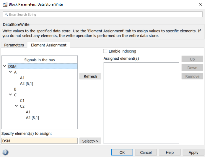
Specify the elements that you want to write to the data store. For example:
In the Signals in the bus list, click
B. Then, click Select to select the elementB.To write all the elements of
A2(in theAnested bus), selectA2[5,1]. Then, click Select.To write the second element of
A2in theC2nested bus, select theA2[5,1]element. In the Specify element(s) to assign text box, edit the text to sayDSM.C.C2.A2(2,1).

For more examples, see Specifying Elements to Assign or Select.
(Optional) Reorder the assigned elements, which changes the order of the ports of the Data Store Write block.
To reorder an assigned element, in the Assigned element(s) list, select the element that you want to move, and click Up or Down.
To remove an assigned element, click Remove.
To apply the assigned elements, click OK.
The Data Store Write block has a port for each assigned element. The names of the selected elements that correspond to each port appear in the block icon. If you assign several signals, these additions may diminish the readability of the model. To improve readability, you can expand the size of the block or create multiple Data Store Write blocks.
Reading Specific Elements from a Data Store
Reading specific elements from a data store involves very similar steps as described in Writing Specific Elements to a Data Store. The Data Store Read block differs slightly from the Data Store Write block. A Data Store Read block has:
An Element Selection pane instead of an Element Assignment pane
A Selected element(s) list instead of an Assigned element(s) list
Specifying Elements to Assign or Select
Use MATLAB matrix element syntax to specify specific elements. For details about specifying matrices in MATLAB, see Creating, Concatenating, and Expanding Matrices.
Note
To select matrix elements with dynamic indexing with the Data Store Read and Data Store Write blocks, select Enable indexing on the Element Selection / Element Assignment pane of the block parameters dialog box. You can select only one element at a time for dynamic indexing. See Data Store Read and Data Store Write.
Valid element specifications. The following table shows examples of valid syntax for specifying elements
to assign or select. These examples use the A2 nested bus
of the A bus, as shown in the bus hierarchy used in Writing Specific Elements to a Data Store.
| Valid Syntax | Description |
|---|---|
DSM.A.A2(:,:) | Selects all elements in every dimension |
DSM.A.A2([1,3,5],1) | Selects the first, third, and fifth elements |
DSM.A.A2(2:5,1) | Selects the second through the fifth element |
Invalid element specifications. The following table shows examples of invalid syntax for specifying
elements to assign or select. These examples use the A2
nested bus of the A bus, as shown in the bus hierarchy
used in Writing Specific Elements to a Data Store.
| Invalid Syntax | Reason the Syntax Is Invalid |
|---|---|
DSM.A.A2(:) | You must specify a colon for each dimension. For the bus hierarchy used in these examples, you must use two colons. |
DSM.A.A2(2:end,1) | You cannot use the |
DSM.A.A2(idx,1) | You cannot use variables to specify indices. Consider using dynamic indexing by selecting Enable indexing on the Element Selection / Element Assignment pane of the block parameters dialog box. See Data Store Read and Data Store Write. |
DSM.A.A2(-1,1) | The dimension |
Specification using the command line. To set the elements to write to or read from, use the
DataStoreElements parameter. Use a pound sign (#) to
delimit multiple elements. For example, select the Data Store
Write or Data Store Read block for which you want
to specify elements and enter a command such as:
set_param(gcb, 'DataStoreElements', 'DSM.A#DSM.B#DSM.C(3,4)')
This specification results in the block now having three ports corresponding to the elements that you specified.
Rename Data Stores
Rename Data Store Defined by Block
Rename a data store everywhere it is used by Data Store Read and Data Store Write blocks in a model.
In a Data Store Memory block dialog box, type a new name in the Data store name box, and click Rename All.
In the Rename All dialog box, confirm the new data store name in the New name field, and click OK.
Note
You cannot use Rename All to rename a data store if
you create a Simulink.Signal object in a workspace to
control the code generated for the data store. Instead, you must rename the
corresponding Simulink.Signal object using Model Explorer.
For an example, see Rename Data Store Defined by Signal Object.
Rename Data Store Defined by Signal Object
This example shows how to rename a data store defined by a
Simulink.Signal object. You can use Model Explorer to
rename the object everywhere it is used by Data Store Read and
Data Store Write blocks in a model or in a model reference
hierarchy.
Open the model
sldemo_mdlref_dsm. The model creates aSimulink.SignalobjectErrorCondin the MATLAB base workspace and uses the object as a global data store in a model reference hierarchy.openExample('sldemo_mdlref_dsm')Open Model Explorer.
In the Model Hierarchy pane, select the base workspace.
In the Contents pane, right-click the data store
ErrorCondand select Rename All.In the Select a system dialog box, click the name of the model
sldemo_mdlref_dsmto select it as the context for renaming the data storeErrorCond. The Update diagram to include recent changes check box is cleared by default to save time by avoiding unnecessary model diagram updates. Select the check box to incorporate recent changes you made to the model by forcing a diagram update.Click OK in response to the message to update the model diagram.
Since you just opened the model, you must update the model diagram at least once before renaming a variable such as
ErrorCond. You could have selected Update diagram to include recent changes in the Select a system dialog box to force an initial diagram update, though you typically use that option when you make changes to the model while performing multiple variable renaming operations.In the Rename All dialog box, type the new name for the data store in the New name box and click OK.
Note
You can rename only variables that the function
Simulink.findVarssupports.The renaming operation changes the name in the current model and in all referenced models.
Customized Data Store Access Functions in Generated Code
Embedded Coder® provides a storage class that you can use to specify customized data store access functions in generated code. See Organize Parameter Data into a Structure by Using Struct Storage Class (Embedded Coder) and Access Data Through Functions with Storage Class GetSet (Embedded Coder).