Model Data Editor
Inspect and edit data items (signals, parameters, and states) in a table that you can sort, group, and filter
Description
The Model Data Editor enables you to inspect and edit data items such as signals, block parameters (for example, the Gain parameter of a Gain block), and data stores in a list that you can sort, group, and filter. You can then configure properties and parameters, such as data types and dimensions, without having to locate the items in the block diagram.
Use the Model Data Editor to configure multiple signals, states, and algorithmic parameters. The Model Data Editor can set only certain parameters and properties such as data types, initial values, and physical units. To work with one model element at a time, open the Property Inspector. To perform batch operations, open the Model Data Editor. For information about how to batch edit block parameter values using the Model Data Editor, see Batch Edit Parameter Values Using Model Data Editor.
For information about setting signal properties and parameters, see Signal Properties.
When creating and debugging a model, you can configure multiple data items at once by selecting the corresponding signals and blocks in the block diagram. Work with the selected items in the Model Data Editor instead of opening individual dialog boxes. Use this technique to more quickly view and compare properties of multiple signals that are close to each other in the diagram, for example, in a subsystem.
Use the Model Data Editor to configure:
Instrumentation for signals and data stores, which allows you to view and collect the simulation values. For example, you can log signals to compare data in the Simulation Data Inspector.
Design attributes such as data type, minimum and maximum value, and physical units. You can use these attributes to:
Specify the values of numeric block parameters.
Control the interaction (interface) between components through Inport and Outport blocks and data stores (see Configure Data Interfaces).
Specify the dimensions of nonscalar signals in a model.
Note
The Model Data Editor does not show information about data items in referenced models (which you reference with Model blocks). To work with data items in a referenced model, open the Model Data Editor in that model.
Columns in the Data Table
Use this table to find more information about the purpose of the columns in the Model Data Editor.
| Column Name | Purpose and More Information |
|---|---|
| Source | Shows the name of the block that defines the data item. For signals, also shows the number of the block port that generates the signal. For workspace variables, shows the name of the workspace or data dictionary that contains the variable. |
| Signal Name or Name | Sets the name of the signal, state, or data store. For information about naming signals, see Signal Names and Labels. For parameters, displays the programmatic name of each parameter. For workspace variables, sets the name of the variable. |
| Data Type | Control Data Types of Signals and Control Block Parameter Data Types |
| Min and Max | Specify Signal Ranges and Specify Minimum and Maximum Values for Block Parameters |
| Dimensions | Determine Signal Dimensions |
| Complexity | Sets the numeric complexity of the data item. |
| Sample Time | What Is Sample Time? |
| Unit | Unit Specification in Simulink Models |
| Test Point | Configure Signals as Test Points |
| Log Data | Iterate Model Design Using the Simulation Data Inspector |
| Resolve | Corresponds to the Signal name must resolve to Simulink signal object check box in the Signal Properties dialog box and similar check boxes in block dialog boxes for states and data stores. See Use Signal Objects. |
| Shared | Corresponds to the Share across model instances parameter of the Data Store Memory block. See Data Store Memory. |
| Initial Value | Sets the initial value of the state or data store. See Initialize Signal Values. |
| Value | Set Block Parameter Values |
| Argument | Configures a variable in a model workspace as a model argument. See Configure Instance-Specific Values for Block Parameters in a Referenced Model. |
| Path | Shows the location of the block in the model and provides a link to the block in the Simulink® Editor. Visible when you click the Change Scope button. |
Two Entries Per Cell in the Data Table
When a cell contains two entries (for instance, in the Data Type column), the entry on the right side of the cell indicates compiled information. The compiled information shows you the value that the data item uses for simulation.
For example, the default data type setting for most signals in a model is
Inherit: Inherit via internal rule. With this
setting, after you update the block diagram, Simulink chooses a specific data type, such as single, for
the signal to use for simulation. In the Model Data Editor, the cell in the
Data Type column shows Inherit: Inherit via
internal rule on the left side and single on the
right side.
Open the Model Data Editor
In the Simulink Toolstrip, on the Modeling tab, click Model Data Editor.
While in the Simulink Editor, press Ctrl+Shift+E.
Examples
In this example, use the Model Data Editor to log signals in different subsystems and referenced models so you can inspect their data using the Simulation Data Inspector.
The Using a Data Dictionary to Manage the Data for a Fuel Control System example model
sldemo_fuelsys_dd represents the fueling system of a
vehicle engine. The referenced model
sldemo_fuelsys_dd_controller controls the rate of fuel
flow to the engine.
First, explore the example models.
Open the example model
sldemo_fuelsys_ddand the referenced modelsldemo_fuelsys_dd_controller.openExample('simulink_automotive/UseDDForFuelContSysExample') sldemo_fuelsys_dd sldemo_fuelsys_dd_controllerIn the
sldemo_fuelsys_dd_controllermodel, navigate to theairflow_calcsubsystem.The Pumping Constant block contains a lookup table that describes the performance of a fuel pump. You can stream the output of this block to the Simulation Data Inspector.
Navigate back to the root of the
sldemo_fuelsys_dd_controllermodel and into thefuel_calcsubsystem.Navigate into the
feedforward_fuel_ratesubsystem.The Outport block named
ff_fuel_ratepasses feedforward information to the fuel rate control algorithm.Navigate back to the
fuel_calcsubsystem and into theswitchable_compensationsubsystem.The Inport block named
ff_fuel_ratecarries the feedforward information. You can stream the output of this Inport block.
Then, log signals for data inspection.
Navigate to the root of the
sldemo_fuelsys_dd_controllermodel.In the Model Data Editor, inspect the Signals tab.
Set the Change view drop-down to
Instrumentation.Activate the Change scope button
 to display the contents of the subsystems.
The Model Data Editor identifies all the signals in the model. The Path column appears.
In the Filter Contents box, type
ff_fuel_rate.The Model Data Editor updates the list of signals to include only those named
ff_fuel_rate. You can click the link in the Path column to view where the signal resides within the model.Select the Log Data check box for the signal whose path is
sldemo_fuelsys_dd_controller/fuel_calc/switchable_compensation.This instructs Simulink to send the data for the logged signals to the Simulation Data Inspector.
Filter the signals again using the text
Pumping Constant.The table contains one row that corresponds to the output of the Pumping Constant block.
Select the Log Data check box for the
Pumping Constantsignal.Simulate the system model,
sldemo_fuelsys_dd. During the simulation, double-click a Manual Switch block, such asEngine Speed Selector, to disturb the fuel control system.When the simulation finishes, the Simulation Data Inspector button
 is highlighted. This indicates that there is data
to inspect and compare. Click the Simulation Data Inspector
button.
is highlighted. This indicates that there is data
to inspect and compare. Click the Simulation Data Inspector
button.In the left pane, expand the Run node that corresponds to the simulation run and select the check boxes for the signals whose data you want to inspect and compare.
The Simulation Data Inspector presents the values for the selected signals on the same graph.
In the example model sldemo_fuelsys_dd_controller,
variables and parameter objects set the values of block parameters. The variables and
objects reside in a data dictionary. Use the Model Data Editor to display these dictionary
entries together in a group.
Open the
sldemo_fuelsys_dd_controllermodel.In the example model, open the Model Data Editor and select the Parameters tab.
Activate the Change scope button to display the contents of the subsystems.
Click the Show/refresh additional information button to display rows that correspond to the dictionary entries.
Right-click the Source column header and select Group by This Column.
The Model Data Editor groups the list by block or workspace (including a group for the dictionary entries).
Find the group labeled Source: Dictionary. Now, you can use the Model Data Editor to inspect and modify the attributes of the variables and objects in the dictionary.
The Model Data Editor allows you to filter a list of data items by using one or a combination of these methods:
To filter the data table through a text search, use the Filter contents box.
To filter based on the blocks or signals that you select in the model, next to the Filter contents box, click the Filter using selection button. Then, as you click blocks and signals in the model, the Model Data Editor shows you only the rows that are relevant to that block or signal. If you lasso multiple blocks or signals, the Model Data Editor shows only the rows that are relevant to those model elements.
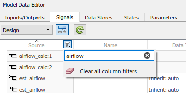
To filter based on column-specific criteria, point to a column header and click the filter icon
 . As you type in the text box, the editor
applies a substring filter to the column contents. After the
filter is applied, the column displays a smaller filter icon
. As you type in the text box, the editor
applies a substring filter to the column contents. After the
filter is applied, the column displays a smaller filter icon
 next to the column header. To edit a
filter, remove a filter, or remove all column filters, click
this icon.
next to the column header. To edit a
filter, remove a filter, or remove all column filters, click
this icon.
In the example model sldemo_househeat, use the Model
Data Editor to log the signals in the Heater subsystem. To
inspect and compare the signals, use the Simulation
Data Inspector.
Open the
sldemo_househeatmodel.openExample('sldemo_househeat')In the
sldemo_househeatmodel, open theHeatersubsystem.Open the Model Data Editor and select the Signals tab.
The Model Data Editor identifies all the signals in the subsystem.
In the Model Data Editor, set the Change view drop-down list to
Instrumentation.Using the Simulink Editor, select all the signals in the subsystem. Optionally, do not select the output of the Constant block because the signal value does not change during the simulation.
In response, the Model Data Editor highlights the rows that correspond to the signals you selected.
In the Model Data Editor, for any of the signals, click the check box in the Log Data column.
The Model Data Editor selects the check box for all of the selected signals.
Simulate the model.
Open the Simulation Data Inspector and, in the leftmost pane, expand the Run node that corresponds to the simulation run. Select the check boxes for the signals whose values you want to inspect and compare.
When you use workspace variables (such as numeric MATLAB® variables and Simulink.AliasType objects) to share settings
between data items, you can interact with those variables through the Model Data Editor.
You do not need to work outside the Editor to configure the data items. In the Editor,
click the Show/refresh additional information button, which finds
variables that the model uses by updating the block diagram.
This example shows how to work with objects that a model uses to set block parameter
values. You modify the value of a variable that the model
sldemo_fuelsys uses.
Open the Model Fault-Tolerant Fuel Control System example model
sldemo_fuelsys.openExample('simulink_automotive/ModelingAFaultTolerantFuelControlSystemExample') sldemo_fuelsysOpen the Model Data Editor Parameters tab.
In the Model Data Editor, click the Show/refresh additional information button.
The data table now contains rows that correspond to variables and objects that the model uses.
In the model, navigate into the
fuel_rate_controlsubsystem and then theairflow_calcsubsystem.In the Model Data Editor, next to the Filter contents box, select the Filter using selection button.
With this button selected, when you select a block or signal in the block diagram, the data table shows only the data items and workspace variables that are relevant to that block or signal.
In the model, click the lookup table block labeled
Pumping Constant.The Model Data Editor shows that the block uses three workspace variables. The block acquires some breakpoint values from the variable
SpeedVect.
Now, you can use the columns in the Model Data Editor to configure the properties of
SpeedVect.
You can further interact with a variable to:
Configure other properties that the columns do not represent:
In the model, open the Property Inspector. On the Modeling tab, under Design, click Property Inspector.
In the Model Data Editor, select the row that corresponds to the target variable or object. If the Property Inspector does not respond, select a different row and then select the target row again.
Use the Property Inspector to configure the target properties.
Move the variable between workspaces and data dictionaries and configure the variable alongside other variables. Use the Model Explorer. To open the Model Explorer, in the Model Data Editor data table, double-click the icon in the leftmost column. For more information about using the Model Explorer, see Edit and Manage Workspace Variables by Using Model Explorer.
Rename a variable everywhere it is used by blocks in Simulink models. In the Model Data Editor, right-click the variable and select Rename All. You can rename only variables that the function
Simulink.findVarssupports.Find blocks that use a specific variable. In the Model Data Editor, right-click the variable and select Find Where Used.
To focus on an individual data item, use one of these techniques:
In the Model Data Editor, next to the Filter contents box, select the Filter using selection button. Then, in the model, click the block or signal that corresponds to the data item.
Use this technique to configure the item by using the columns in the data table.
In the model, open the Property Inspector. On the Modeling tab, under Design, click Property Inspector. Then, in the data table, click the target row. The Property Inspector shows the properties of the data item. If the Property Inspector does not respond when you click the target row, click a different row and then click the target row again.
Use this technique to inspect all of the properties that the Model Data Editor can access at once (in other words, the union of the columns available in the
DesignandInstrumentationviews).In the model, open the Property Inspector. Then, in the data table, for the target row, double-click the cell in the leftmost column (the icon). In the model, select the highlighted block or signal.
Use this technique to inspect all properties, including those that the Model Data Editor cannot access.
To navigate from a data item in the Model Data Editor to the block in the diagram that owns the data item, double-click the icon in the left-most column. The Simulink Editor then focuses on the relevant block. Use this technique to navigate to blocks when you select Change scope to view the contents of subsystems below the current system.
Related Examples
Limitations
You cannot access these attributes by using the Model Data Editor:
Any settings related to code generation. Instead, use the Code Mappings editor or code mappings API.
For mask parameters:
Any settings for tunable mask parameters other than the parameter value.
Any settings for nontunable mask parameters.
Note that some built-in blocks are masked and can have tunable or nontunable mask parameters.
Any settings for parameters of Simscape™ blocks.
Any settings for data items in referenced models. Instead, open the Model Data Editor in the referenced models.
Any settings for variables that are not defined in the base workspace, a model workspace, or a data dictionary. For example, you cannot access the attributes of variables created by mask initialization code.
On the Parameters tab, the data type, minimum value, and maximum value of a Constant block. Use the Signals tab instead.
For some settings that you cannot access with the Model Data Editor, you can use the Property Inspector instead. Open the Property Inspector and select the target data item in the model, not in the Model Data Editor. For mask parameters, use the mask dialog box or the Mask Editor as described in Masking Fundamentals.
The Model Data Editor does not show Stateflow® data. However, the Model Data Editor shows the data for Simulink functions that you define inside Stateflow charts.
To manage Stateflow data, events, and messages in a chart, see Stateflow Editor (Stateflow).
On the Parameters tab, these variables are not available:
Variables used by non-tunable block parameters. For example, the minimum and maximum parameters on a Gain block or the
Sample
									time
on a Constant block.Variant control variables
Variables used for symbolic dimensions
Version History
Introduced in R2016b