CIC Interpolator
R2026bCIC Interpolator block
To add a block to a model, double-click the canvas and start typing the block name. Then, select the block from the list.
Libraries:
DSP HDL Toolbox /
Filtering
Description
The CIC Interpolator block interpolates an input signal by using a cascaded integrator-comb (CIC) interpolation filter. CIC interpolation filters are a class of linear phase finite impulse response (FIR) filters consisting of a comb part and an integrator part. The CIC interpolation filter structure consists of N sections of cascaded comb filters, a rate change factor of R, and N sections of cascaded integrators. For more information about CIC interpolation filters, see Algorithms.
The block supports these combinations of input and output data.
Scalar input and scalar output — Support for fixed and variable interpolation rates
Scalar input and vector output — Support for fixed interpolation rates only
Vector input and vector output — Support for fixed interpolation rates only
The block provides an architecture suitable for HDL code generation and hardware deployment.
Note
You can also generate HDL code for this hardware-optimized algorithm, without creating a Simulink® model, by using the DSP HDL IP Designer app. The app provides the same interface and configuration options as the Simulink block.
Examples
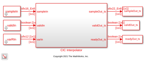
Implement CIC Interpolator Filter for HDL
Filter and upsample data by using the CIC Interpolator block.
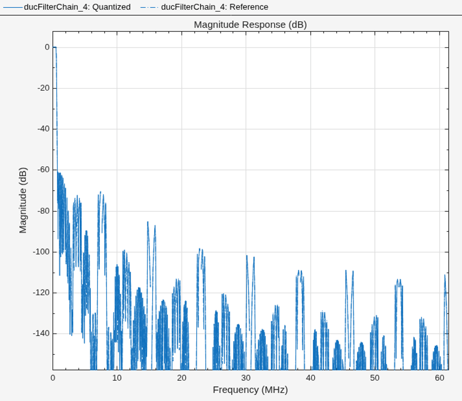
Implement Digital Upconverter for FPGA
Design a digital upconverter (DUC) for LTE on FPGAs.
Ports
Input
Input data, specified as a scalar or a column vector with a length from 1 to 64. The input data must be a signed integer or signed fixed point with a word length less than or equal to 32.
The block has an output ready signal that indicates when the block is ready to process new input data. Your design can react to the ready signal to provide the next input sample, or you can space your input data with enough cycles in between that the block can process each sample. For more information, see Backpressure Signal.
While processing the input data, the block implements the rounding method
Floor and the overflow action Wrap. For more
details, see Rounding Modes and Overflow Handling.
Data Types: int8 | int16 | int32 | signed fixed point
Complex Number Support: Yes
Control signal that indicates if the input data is valid. The block sets this
output to 1 (true) when it can accept data, and
to 0 (false) when it is processing and cannot
accept more data. For more information, see Backpressure Signal.
Data Types: Boolean
Use this port to dynamically specify the variable interpolation rate during run time.
This value must have the data type fixdt(0,12,0) and must be an
integer in the range from 1 to the Interpolation factor (Rmax)
parameter value.
Dependencies
To enable this port, on the Main tab, set the
Interpolation factor source parameter to Input
port.
Data Types: fixdt(0,12,0)
Control signal that clears internal states. When reset is
1 (true), the block stops the current
calculation and clears internal states. When the reset is
0 (false) and the input
valid is 1 (true), the
block captures data for processing.
For more reset considerations, see the Reset Signal section on the Hardware Control Signals page.
Dependencies
To enable this port, on the Control Ports tab, select the Enable reset input port parameter.
Data Types: Boolean
Output
CIC-interpolated output data, returned as a scalar or a column vector with a length from 1 to 64. You can define the data type of this output by setting the Output data type parameter on the Data Types tab.
Data Types: int8 | int16 | int32 | signed fixed point
Complex Number Support: Yes
Control signal that indicates if the data from the output
data port is valid. When valid is
1 (true), the block returns valid data from
the output data port. When valid is
0 (false), the values from the output
data port are not valid.
Data Types: Boolean
Control signal that indicates that the block can accept new input data. The block
sets this output to 1 (true) when it can accept
data, and to 0 (false) when it is processing and
cannot accept more data. For more information, see Backpressure Signal.
Data Types: Boolean
Parameters
Note
These parameters apply when configuring a block in Simulink or an algorithm in the DSP HDL IP Designer app.
Main
Select whether the block operates with a fixed or variable interpolation rate.
Property— Use a fixed interpolation rate specified from the Interpolation factor (R) parameter.Input port— Use a variable interpolation rate specified from the R input port.
Note
The block does not support variable interpolation for these two combinations of input and output:
Scalar input and vector output
Vector input and vector output
Specify the interpolation factor rate at which the block interpolates the input. This value must be an integer. The range of available values depends on the type of input and output data.
| Input Data | Output Data | Interpolation factor (R) Valid Values |
|---|---|---|
| Scalar | Scalar | Integer from 1 to 2048 |
| Scalar | Vector | Integer from 1 to 64 |
| Vector | Vector | Integer from 1 to 64 |
Note
For vector inputs, select the interpolation factor rate and input vector length such that their multiplication value does not exceed 64.
Dependencies
To enable this parameter, set the Interpolation factor
source parameter to Property.
Specify the upper bound of the range of valid values for the R input port.
Note
The block does not support variable interpolation for these two combinations of input and output:
Scalar input and vector output
Vector input and vector output
Dependencies
To enable this parameter, set the Interpolation factor
source parameter to Input port.
Specify the differential delay of the comb part of the block.
Specify the number of sections in either the comb part or the integrator part of the block.
Specify the minimum number of cycles between the valid input samples as
1, factors of R, or multiples of
R based on the type of input and output data, where
R is the interpolation factor.
| Input Data | Output Data | Minimum Number of Cycles Between Valid Input Samples |
|---|---|---|
| Scalar | Scalar | greater than or equal to R |
| Scalar | Vector | factors less than R |
| Vector | Vector | 1 |
Dependencies
To enable this parameter, set the Interpolation factor
source parameter to Property.
Select this parameter to compensate for the output gain of the block.
The latency of the block changes depending on the type of input, the interpolation you specify, the number of sections, and the value of this parameter. For more information on the latency of the block, see Latency.
Data Types
Select the data type for the output data.
Full precision— The output data type has a word length equal to the input word length plus gain bits.Same word length as input— The output data type has a word length equal to the input word length.Minimum section word lengths— The output data type uses the word length you specify in the Output word length parameter.
Specify the word length of the output as an integer from 2 to 104.
Dependencies
To enable this parameter, set the Output data type
parameter to Minimum section word lengths.
Control Ports
Select this parameter to enable the reset input port. The reset signal implements a local synchronous reset of the data path registers.
For more reset considerations, see the Reset Signal section on the Hardware Control Signals page.
Select this parameter to connect the generated HDL global reset signal to the data path registers. This parameter does not change the appearance of the block or modify simulation behavior in Simulink. When you clear this parameter, the generated HDL global reset clears only the control path registers. The generated HDL global reset can be synchronous or asynchronous depending on the HDL Code Generation > Global Settings > Reset type parameter in the model Configuration Parameters.
For more reset considerations, see the Reset Signal section on the Hardware Control Signals page.
Algorithms
The transfer function of a CIC interpolation filter is
HC is the transfer function of the comb part of the CIC filter.
HI is the transfer function of the integrator part of the CIC filter.
N is the number of sections in either the comb part or integrator part of the filter. This value does not represent the total number of sections throughout the entire filter.
R is the interpolation factor.
M is the differential delay.
The CIC Interpolator block has the CIC filter structure shown in this figure. The structure consists of N sections of cascaded comb filters, a rate change factor of R, and N sections of cascaded integrators [1].

You can locate the unit delay in the integrator part of the CIC filter in either the feedforward or feedback path. These two configurations yield an identical filter frequency response. However, the numerical outputs from these two configurations are different due to the latency of the block. Because this configuration is preferred for HDL implementation, this block puts the unit delay in the feedforward path of the integrator.
The block upsamples the comb stage output using R, either using the fixed interpolation rate provided using the Interpolation factor (R) parameter or the variable interpolation rate provided using the R input port. At the upsampling stage, the block uses a counter to count the valid input samples, which depend on the interpolation rate. Whenever the interpolation rate changes, the block resets and starts a new calculation from the next sample. This mechanism prevents the block from accumulating false values. Then, the block provides the interpolated output to the integrator part of the CIC filter.
The gain of the CIC interpolation filter at each stage is given by
Gi is the gain at ith stage.
R is the Interpolation factor (R) parameter value.
M is the Differential delay (M) parameter value.
N is the Number of sections (N) parameter value.
The output of the block is amplified by a specific gain value. This gain equals the gain of the 2Nth stage of the CIC interpolation filter and is given by .
The block implements gain correction in two parts: coarse gain and fine gain. In coarse gain correction, the block calculates the shift value, adds the shift value to the fractional bits to create a numeric type, and performs a bit-shift left and reinterpretcast. In fine gain correction, the block divides the remaining gain with the coarse gain if the gain is not a power of 2. Then, the block multiplies the corrected coarse gain value by the inverse value of the fine gain. Before the block starts processing, all possible shift and fine gain values are precalculated and stored in an array.
You can modify this equation to . In this equation, cGain is the coarse gain and fGain is the fine gain. These gains are given by these equations.
To perform gain correction when the Interpolation factor source
parameter is set to Input port, the block sets the output data
type configured with the maximum interpolation rate and bit-shifts left for all of the
values under the maximum interpolation rate. The bit-shift value is equal to .
The block outputs data based on the output data type selection. Consider a block with R, M, and N values of 8, 1, and 3, respectively, and an input width of 16. The word length at the ith internal stage is calculated as , where:
Gi is the gain at ith stage.
BIn is the input word length.
Bi is the word length at ith stage.
The output word length is calculated as , where BOut is the output word length.
When you set the Output data type parameter to Full
precision, the block outputs data with a word length of 22 by adding 6 gain
bits to the input word length of 16. The word lengths of the internal comb and integrator
stages are set to accommodate the bit growth.
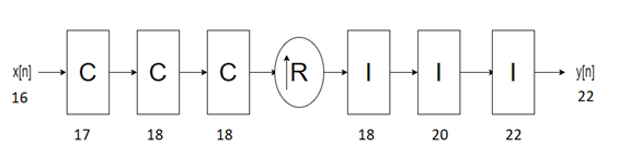
When you set the Output data type parameter to Same
word length as input, the block outputs data with a word length of 16, which
is the same length as the input word length. The word lengths of the internal comb and
integrator stages are set in the same way as in Full precision
mode.
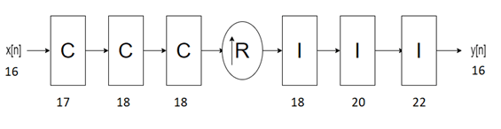
When you set the Output data type parameter to Minimum
section word lengths and the Output word length
parameter to 16, the block outputs data with a word length of 16. The
word lengths of the internal comb and integrator stages are set in the same way as in
Full precision mode.

The latency of the block changes depending on the type of input, the interpolation you specify, the number of sections, the value of the Gain correction parameter, and the value of the Minimum number of cycles between valid input samples parameter. This table shows the latency of the block. N is the number of sections, vecLen is the length of the vector, and R is the interpolation factor.
| Input Data | Output Data | Interpolation Type | Gain Correction | Minimum number of cycles between valid input samples (NumCycles) | Latency in Clock Cycles |
|---|---|---|---|---|---|
| Scalar | Scalar | Fixed | off | NumCycles is equal to R or greater than R |
|
on | NumCycles is equal to R or greater than R |
| |||
| Scalar | Vector | Fixed | off | NumCycles is equal to 1 or less than R | 4 + N + ((R x vecLen) + 2) x N. |
on | NumCycles is equal to 1 or less than R | 4 + N + ((R x vecLen) + 2) x N + 9. | |||
| Vector | Vector | Fixed | off | NumCycles is equal to 1 |
|
on | NumCycles is equal to 1 |
|
Note
The block does not support variable interpolation for these two combinations of input and output:
Scalar input and vector output
Vector input and vector output
This section shows the output of the block for a scalar input with different R, M, and N values.
This figure shows the output of the block with the default configuration (that is, with a fixed interpolation rate and R, M, and N values of 2, 1, and 2, respectively). The latency of the block is 5 clock cycles and is calculated as 3 + N, where N is the number of sections.

This figure shows the output of the block with a fixed interpolation rate, R, M, and N values of 8, 1, and 3, respectively, and the Gain correction parameter selected. The latency of the block is 15 clock cycles and is calculated as 3 + N + 9, where N is the number of sections.

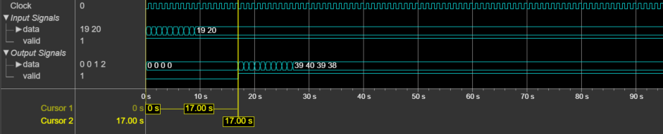
This section shows the output of the block for a vector input with different R, M, and N values.
This figure shows the output of the block for a two-element column vector input with the default configuration (that is, with a fixed interpolation rate and R, M, and N values of 2, 1, and 2, respectively). The latency of the block is 17 clock cycles.
This figure shows the output of the block for an eight-element column vector input with a fixed interpolation rate, R, M, and N values of 8, 1, and 3, respectively, and the Gain correction parameter selected. The latency of the block is 213 clock cycles.

The performance of the synthesized HDL code varies with your target and synthesis options. It also varies based on the input data type.
This table shows the resource and performance data synthesis results of the block for a
scalar input with fixed and variable interpolation rates and for a two-element column vector
of type fixdt(1,16,0) with a fixed interpolation rate when
R, M, and N are 2, 1, and 2,
respectively. The generated HDL code is targeted to the AMD®
Zynq®- 7000 ZC706 Evaluation Board.
| Input Data | Interpolation Type | Slice LUTs | Slice Registers | Maximum Frequency in MHz |
|---|---|---|---|---|
| Scalar | Fixed rate | 68 | 90 | 844.12 |
| Variable rate | 143 | 115 | 451.83 | |
| Vector | Fixed rate | 480 | 921 | 376.51 |
The resources and frequencies vary based on the type of input data, R, M, and N values, and other parameter values selected in the block mask. Using a vector input can increase the throughput, however, doing so also increases the number of hardware resources that the block uses.
References
[1] Hogenauer, E. “An Economical Class of Digital Filters for Decimation and Interpolation.” IEEE Transactions on Acoustics, Speech, and Signal Processing 29, no. 2 (April 1981): 155–62. https://doi.org/10.1109/TASSP.1981.1163535.
Extended Capabilities
This block supports C/C++ code generation for Simulink accelerator and rapid accelerator modes and for DPI component generation.
HDL Coder™ provides additional configuration options that affect HDL implementation and synthesized logic.
This block has one default HDL architecture.
| ConstrainedOutputPipeline | Number of registers to place at
the outputs by moving existing delays in the design. Distributed pipelining
does not redistribute these registers. The default value is
|
| InputPipeline | Number of input pipeline stages
to insert in the generated code. Distributed pipelining and constrained
output pipelining can move these registers. The default value is
|
| OutputPipeline | Number of output pipeline stages
to insert in the generated code. Distributed pipelining and constrained
output pipelining can move these registers. The default value is
|
| SynthesisAttributes |
Specifies the synthesis attributes for the blocks and block output signals in the model. The generated HDL code contains these attributes. For more information, see SynthesisAttributes (HDL Coder). |
Version History
Introduced in R2022a
MATLAB Command
You clicked a link that corresponds to this MATLAB command:
Run the command by entering it in the MATLAB Command Window. Web browsers do not support MATLAB commands.
Select a Web Site
Choose a web site to get translated content where available and see local events and offers. Based on your location, we recommend that you select: .
You can also select a web site from the following list
How to Get Best Site Performance
Select the China site (in Chinese or English) for best site performance. Other MathWorks country sites are not optimized for visits from your location.
Americas
- América Latina (Español)
- Canada (English)
- United States (English)
Europe
- Belgium (English)
- Denmark (English)
- Deutschland (Deutsch)
- España (Español)
- Finland (English)
- France (Français)
- Ireland (English)
- Italia (Italiano)
- Luxembourg (English)
- Netherlands (English)
- Norway (English)
- Österreich (Deutsch)
- Portugal (English)
- Sweden (English)
- Switzerland
- United Kingdom (English)

