Model Vision Sensor Detections
This example shows how to model and simulate the output of an automotive vision sensor for different driving scenarios. Generating synthetic vision detections is important for testing and validating tracking and sensor fusion algorithms in corner cases or when sensor hardware is unavailable. This example analyzes the differences between vision measurements and vehicle ground truth position and velocity for a forward collision warning (FCW) scenario, a passing vehicle scenario, and a hill descent scenario.
In this example, you generate vision detections programmatically. You can also generate detections by using the Driving Scenario Designer app. For an example, see Create Driving Scenario Interactively and Generate Synthetic Sensor Data.
Introduction
Vehicles that contain advanced driver assistance system (ADAS) features or are designed to be fully autonomous typically rely on multiple types of sensors. These sensors include sonar, radar, lidar, and vision. A robust solution includes a sensor fusion algorithm to combine the strengths across the various types of sensors included in the system. For more information about sensor fusion of synthetic detections from a multisensor ADAS system, see Sensor Fusion Using Synthetic Radar and Vision Data.
When using synthetic detections for testing and validating tracking and sensor fusion algorithms, it is important to understand how the generated detections model the sensor's unique performance characteristics. Each kind of automotive sensor provides a specific set of strengths and weaknesses which contribute to the fused solution. This example presents some important performance characteristics of automotive vision sensors and shows how the sensor performance is modeled by using synthetic detections.
Vision Sensor Model
This example uses visionDetectionGenerator to generate synthetic vision sensor detections. visionDetectionGenerator models the following performance characteristics of automotive vision sensors:
Strengths
Good lateral position and velocity accuracy
One detection reported per target
Weaknesses
Poor longitudinal position and velocity accuracy
Inability to detect occluded targets
Longitudinal biases for elevated targets
FCW Driving Scenario
Create a forward collision warning (FCW) test scenario, which is used to illustrate how to measure a target's position with an automotive vision sensor. The scenario consists of a moving ego vehicle and a stationary target vehicle placed 75 meters down the road. The ego vehicle has an initial speed of 50 kph before applying its brakes to achieve a constant deceleration of 3 m/s^2. The vehicle then comes to a complete stop 1 meter before the target vehicle's rear bumper.
rng default;
initialDist = 75;  % m
finalDist = 1;     % m
initialSpeed = 50; % kph
brakeAccel = 3;    % m/s^2
[scenario, egoCar] = helperCreateSensorDemoScenario('FCW', initialDist, initialSpeed, brakeAccel, finalDist);
Forward-Facing Vision Sensor
Create a forward-facing vision sensor mounted on the ego vehicle's front windshield, 1.1 m above the ground. The sensor is pitched down 1 degree toward the road and generates measurements every 0.1 second. The sensor's camera has a 480-by-640 pixel imaging array and a focal length of 800 pixels. The sensor can locate objects within a single image with an accuracy of 5 pixels and has a maximum detection range of 150 m. The ActorProfiles property specifies the physical dimensions of the vehicles seen by the vision sensor in the simulation.
visionSensor = visionDetectionGenerator(...
    'SensorIndex', 1, ...
    'UpdateInterval', 0.1, ...
    'SensorLocation', [0.75*egoCar.Wheelbase 0], ...
    'Height', 1.1, ...
    'Pitch', 1, ...
    'Intrinsics', cameraIntrinsics(800, [320 240], [480 640]), ...
    'BoundingBoxAccuracy', 5, ...
    'MaxRange', 150, ...
    'ActorProfiles', actorProfiles(scenario))
visionSensor =

  visionDetectionGenerator with properties:

               SensorIndex: 1
            UpdateInterval: 0.1000

            SensorLocation: [2.1000 0]
                    Height: 1.1000
                       Yaw: 0
                     Pitch: 1
                      Roll: 0
                Intrinsics: [1×1 cameraIntrinsics]

            DetectorOutput: 'Objects only'
               FieldOfView: [43.6028 33.3985]
                  MaxRange: 150
                  MaxSpeed: 100
       MaxAllowedOcclusion: 0.5000
        MinObjectImageSize: [15 15]

      DetectionProbability: 0.9000
    FalsePositivesPerImage: 0.1000

  Use get to show all properties
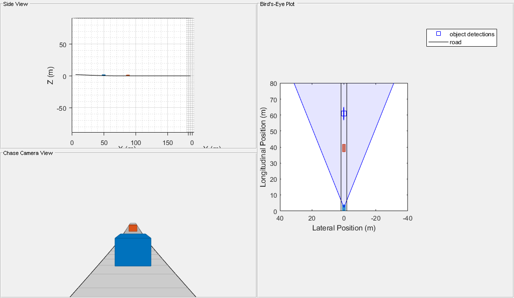
Simulation of Vision Detections
Simulate the vision sensor measuring the position of the target vehicle by advancing the simulation time of the scenario. The vision sensor generates detections from the true target pose (position, velocity, and orientation) expressed in the ego vehicle's coordinate frame.
The vision sensor is configured to generate detections at 0.1-second intervals, which is consistent with the update rate of typical automotive vision sensors. However, to accurately model the motion of the vehicles, the scenario simulation advances every 0.01 seconds. The sensor returns a logical flag, isValidTime, that is true when the vision sensor reaches its required update interval, indicating that this simulation time step will generate detections.
% Create display for FCW scenario
[bep, figScene] = helperCreateSensorDemoDisplay(scenario, egoCar, visionSensor);

metrics = struct;                 % Initialize struct to collect scenario metrics
while advance(scenario)           % Update vehicle positions
    gTruth = targetPoses(egoCar); % Get target positions in ego vehicle coordinates

    % Generate time-stamped vision detections
    time = scenario.SimulationTime;
    [dets, ~, isValidTime] = visionSensor(gTruth, time);

    if isValidTime
        % Update Bird's-Eye Plot with detections and road boundaries
        helperUpdateSensorDemoDisplay(bep, egoCar, visionSensor, dets);

        % Collect vision detections and ground truth for offline analysis
        metrics = helperCollectScenarioMetrics(metrics, gTruth, dets);
    end

    % Take a snapshot for the published example
    helperPublishSnapshot(figScene, time>=6);
end

Position Measurements
Over the duration of the FCW test, the target vehicle's distance from the ego vehicle spans a wide range of values. By comparing the vision sensor's measured longitudinal and lateral positions of the target vehicle to the target vehicle's ground truth position, you can observe the accuracy of the sensor's measured positions.
Use helperPlotSensorDemoDetections to plot the longitudinal and lateral position errors as the difference between the measured position reported by the vision sensor and the target vehicle's ground truth. The ground truth reference for the target vehicle is the point on the ground directly below the center of the target vehicle's rear axle, which is 1 meter in front of the car's bumper.
helperPlotSensorDemoDetections(metrics, 'position', 'reverse range', [-6 6]);

% Show rear overhang of target vehicle
tgtCar = scenario.Actors(2);
rearOverhang = tgtCar.RearOverhang;

subplot(1,2,1);
hold on; plot(-rearOverhang*[1 1], ylim, 'k'); hold off;
legend('Error', '2\sigma noise', 'Rear overhang');

The vision sensor converts the target's position in the camera's image to longitudinal and lateral positions in the ego vehicle's coordinate system. The sensor does this conversion by assuming that the detected points in the image lie on a flat road that is at the same elevation as the ego vehicle.
Longitudinal Position Measurements
For a forward-facing vision sensor configuration, longitudinal position measurements are derived primarily from the target's vertical placement in the camera's image.
An object's vertical position in the image is strongly correlated to the object's height above the road, but it is weakly correlated to the object's distance from the camera. This weak correlation causes a monocular vision sensor's longitudinal position errors to become large as an object moves away from the sensor. The longitudinal position errors in the preceding plot on the left show how the sensor's longitudinal errors quickly increase when the target vehicle is far from the sensor. The sensor's longitudinal  measurement noise is less than 1 meter when the ground truth range to the target vehicle is less than 30 meters, but grows to more than 5 meters at ranges beyond 70 meters from the ego vehicle.
The longitudinal position errors also show a -1 meter bias between the longitude measured by the vision sensor and the target's ground truth position. The -1 meter bias indicates that the sensor consistently measures the target to be closer to the ego vehicle than the target vehicle's ground truth position. Instead of approximating the target as a single point in space, the vision sensor models the physical dimensions of the vehicle's body. For the FCW scenario, the vision sensor views the target vehicle's rear side. The -1 meter bias in the detections generated from this side corresponds to the vehicle's rear overhang. A vehicle's rear overhang defines the distance between the vehicle's rear side and its rear axle, which is where the ground truth reference is located.
Lateral Position Measurements
For a forward-facing vision sensor configuration, lateral position is derived from the target's horizontal location in the camera's image.
Unlike longitudinal position, an object's lateral position is strongly correlated to its horizontal position in the vision sensor's image. This strong correlation produces accurate lateral position measurements that do not degrade quickly with an object's distance from the sensor. The lateral position errors in the preceding plot on the right grow slowly with range. The measurement noise reported by the sensor remains below 0.2 meters out to a ground truth range of 70 meters.
Velocity Measurements and Target Occlusion
Create a driving scenario with two target vehicles (a lead car and a passing car) to illustrate the accuracy of a vision sensor's longitudinal and lateral velocity measurements. The lead car is placed 40 meters in front of the ego vehicle and is traveling with the same speed. The passing car starts in the left lane alongside the ego vehicle, passes the ego vehicle, and merges into the right lane just behind the lead car. This merging maneuver generates longitudinal and lateral velocity components, enabling you to compare the sensor's accuracy along these two dimensions.
Because the lead car is directly in front of the sensor, it has a purely longitudinal velocity component. The passing car has a velocity profile with both longitudinal and lateral velocity components. These components change as the car passes the ego vehicle and moves into the right lane behind the lead car. Comparing the sensor's measured longitudinal and lateral velocities of the target vehicles to their ground truth velocities illustrates the vision sensor's ability to observe both of these velocity components.
% Create passing scenario
leadDist = 40;     % m
speed = 50;        % kph
passSpeed = 70;    % kph
mergeFract = 0.55; % Merge 55% into right lane
[scenario, egoCar] = helperCreateSensorDemoScenario('Passing', leadDist, speed, passSpeed, mergeFract);

Configuration of Vision Sensor Velocity Measurements
The vision sensor cannot determine an object's velocity from a single image. To estimate velocity, the vision sensor compares the object's movement between multiple images. The extracted target positions from multiple images are processed by using a smoothing filter. In addition to estimating velocity, this filter produces a smoothed position estimate. To adjust the amount of smoothing that the filter applies, you can set the sensor's process noise intensity. The sensor's process noise should be set to be of the order of the maximum acceleration magnitude expected from a target that must be detected by the sensor.
Take the vision sensor used in the previous section, and configure it to generate position and velocity estimates from a smoothing filter with a process noise intensity of 5 m/s^2.
% Configure vision sensor's noise intensity used by smoothing filter
release(visionSensor);
visionSensor.ProcessNoiseIntensity = 5; % m/s^2

% Use actor profiles for the passing car scenario
visionSensor.ActorProfiles = actorProfiles(scenario);
Use helperRunSensorDemoScenario to simulate the motion of the ego and target vehicles. This function also collects the simulated metrics, as was previously done for the FCW driving scenario.
snapTime = 5.9; % Simulation time to take snapshot for publishing
metrics = helperRunSensorDemoScenario(scenario, egoCar, visionSensor, snapTime);

Use helperPlotSensorDemoDetections to plot the vision sensor's longitudinal and lateral velocity errors as the difference between the measured velocity reported by the sensor and the target vehicle's ground truth.
helperPlotSensorDemoDetections(metrics, 'velocity', 'time', [-25 25]);
subplot(1,2,1);
legend('Lead car error', 'Lead car 2\sigma noise', 'Pass car error', 'Pass car 2\sigma noise');
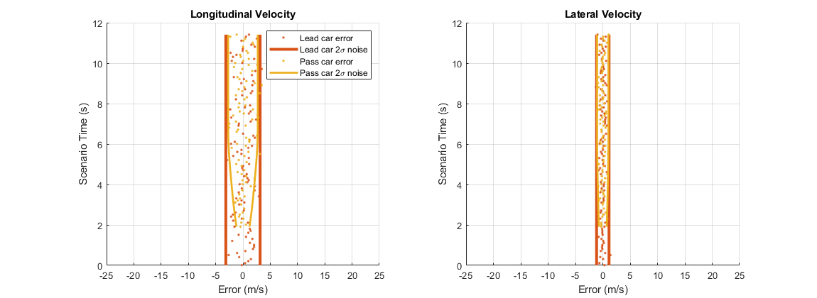
Longitudinal Velocity Measurements
Forward-facing vision sensors measure longitudinal velocity by comparing how the sensor's longitudinal position measurements change between sensor update intervals. Because the sensor's longitudinal position errors grow with range, the longitudinal velocity errors will also grow with increasing target range.
The longitudinal velocity errors from the passing vehicle scenario are shown in the preceding plot on the left. Because the lead car maintains a constant distance from the vision sensor, its errors (displayed as red points) show the same measurement noise throughout the scenario. However, the passing car's distance from the sensor is not constant, but this distance increases as the car passes the sensor and moves toward the lead car. The passing car's longitudinal velocity errors (displayed as yellow points) are small when it first enters the sensor's field of view at 2 seconds. The passing car is close to the vision sensor at this point in the scenario. From 2 seconds to 6 seconds, the passing car is moving away from the ego vehicle and approaching the lead car. Its longitudinal velocity errors grow as its distance from the sensor increases. Once the passing car merges into the right lane behind the lead car, it maintains a constant distance from the sensor, and its measurement noise remains constant.
Lateral Velocity Measurements
Forward-facing vision sensors measure lateral velocity by comparing how the sensor's lateral position measurements change between sensor update intervals. Because the sensor's lateral position errors are not strongly correlated with the target's range from the sensor, the lateral velocity errors will also show little dependence on target range.
The lateral velocity errors from the passing vehicle scenario are shown in the preceding plot on the right. The errors from the lead car (red points) and the passing car (yellow points) have nearly the same measurement noise for the entire scenario. The passing car's reported lateral velocity errors show little change as it moves away from the sensor.
Detection of Targets with Partial Occlusion
In the preceding velocity error plots, the lead car (red points) is reliably detected during the first 6 seconds of the scenario. The passing car (yellow points) is detected at 2 seconds when it first enters the camera's field of view. Detections are then generated on both of the target vehicles until 6 seconds. At 6 seconds, the passing car merges into the right lane and moves between the ego vehicle and the lead car. For the remainder of the scenario, the passing car partially occludes the vision sensor's view of the lead car. 55% of the lead car's rear side is occluded, leaving only 45% visible to the sensor for detection. This occluded view of the lead car prevents the sensor from finding the car in the camera's image and generating detections.
A vision sensor's ability to provide reliable detections is strongly dependent on an unobstructed view of the object it is detecting. In dense traffic, the visibility of vehicles in the scenario can change rapidly as distances between vehicles change and vehicles move in and out of lanes. This inability to maintain detection on obstructed targets poses a challenge to tracking algorithms processing the vision sensor's detections.
Rerun the passing vehicle scenario with a vision sensor that can detect targets with as much as 60% of the target's viewable area occluded.
% Configure vision sensor to support maximum occlusion of 60%
release(visionSensor);
visionSensor.MaxAllowedOcclusion = 0.6;

% Run simulation and collect detections and ground truth for offline analysis
metrics = helperRunSensorDemoScenario(scenario, egoCar, visionSensor);

% Plot longitudinal and lateral velocity errors
helperPlotSensorDemoDetections(metrics, 'velocity', 'time', [-25 25]);
subplot(1,2,1);
legend('Lead car error', 'Lead car 2\sigma noise', 'Pass car error', 'Pass car 2\sigma noise');
In the preceding plot, velocity errors are shown for both the lead car (red points) and the passing car (yellow points). The same error performance is observed as before, but now detections on the lead car are maintained after the passing car has merged behind it at 6 seconds. By adjusting the maximum allowed occlusion, you can model a vision sensor's sensitivity to target occlusion.
Longitudinal Position Bias from Target Elevation
An object's vertical location in the camera's image is strongly correlated to its height above the road. Because a monocular vision sensor generates longitudinal position measurements from the vertical location of objects in its camera's image, large errors can arise for targets at different elevations from the ego vehicle. When an object changes elevation, the sensor incorrectly interprets the vertical displacement in the camera's image as a change in the object's longitudinal position.
Run the FCW scenario again with a stationary target vehicle placed at a location 2 meters lower than the initial position of the ego vehicle. The ego vehicle descends a small hill as it approaches the target vehicle. As the ego vehicle descends the hill, the target vehicle's vertical location in the camera's image changes, introducing a bias in the sensor's measured longitudinal position.
% Create FCW hill descent scenario
initialDist = 75;  % m
finalDist = 1;     % m
initialSpeed = 50; % kph
brakeAccel = 3;    % m/s^2
[scenario, egoCar] = helperCreateSensorDemoScenario('FCW', initialDist, initialSpeed, brakeAccel, finalDist, false, 2);

% Use actor profiles for the FCW hill descent scenario
release(visionSensor);
visionSensor.ActorProfiles = actorProfiles(scenario);

% Run simulation and collect detections and ground truth for offline analysis
snapTime = 3; % Simulation time to take snapshot for publishing
metrics = helperRunSensorDemoScenario(scenario, egoCar, visionSensor, snapTime, true);

Plot the position errors generated for the target vehicle as the ego vehicle descends the small hill.
helperPlotSensorDemoDetections(metrics, 'position', 'reverse range', [-6 6;0 80]);
subplot(1,2,1); xlim([-10 60]); ylim([0 80]);
legend('Error', '2\sigma noise');

The preceding plots show the longitudinal position errors (on the left) and the lateral position errors (on the right) for the hill descent scenario. Note that in the longitudinal position error plot, the limits of the error axis have been increased to accommodate the large bias induced by the target's elevation relative to the camera sensor as the ego vehicle descends the hill.
The ego vehicle begins its descent when it is 75 meters away from the target vehicle. Because the ego vehicle is pitched down as it descends the hill, the target appears at an elevated position near the top of the camera's image. As the ego vehicle descends the hill, the target vehicle's location in the camera's image moves from the top of the image and crosses the horizon line. For monocular vision sensors, targets located near the horizon line in the camera's image are mapped to positions that are very far from the sensor. (By definition, points on the horizon line are located at infinity.) The vision sensor does not generate detections for objects appearing above the horizon in the camera's image, because these points do not map to locations on the road's surface.
Large changes in the vehicle's longitudinal position as its location in the image moves away from the horizon also cause the sensor's smoothing filter to generate large longitudinal velocity estimates. The sensor rejects detections with speeds exceeding its MaxSpeed property. These large longitudinal velocities produced by the target's elevation also prevent the sensor from generating detections when the target vehicle is near the camera's horizon.
When the ego vehicle is approximately 40 meters from the target vehicle, the target vehicle's image location has crossed the horizon line and the sensor's velocity estimates satisfy its max speed constraint. At this distance, the vision sensor begins to generate detections from the target vehicle. The mapping of target locations near the camera's horizon to points on the road far from the sensor explains the large longitudinal errors modeled by the monocular vision sensor when it begins detecting the target vehicle. The longitudinal bias continues to decrease as the ego vehicle approaches the bottom of the hill and the target's location moves away from the horizon line in the camera's image. At the end of the ego vehicle's descent, the target is at the same elevation as the ego vehicle. Only the -1 meter bias corresponding to the target vehicle's rear overhang is present. The sensor's lateral position errors show no bias, because the pitch of the ego vehicle as it descends the hill does not change the target's horizontal location in the camera's image.
Pedestrian and Vehicle Detection
A vision sensor's ability to detect an object in its camera's image depends on the number of pixels the object occupies in the image. When an object's size in the image is large (hundreds of pixels), the sensor can easily identify the object and generate a detection. However when an object's size in the image is small (tens of pixels) the sensor might not find it and will not generate a detection. An object's projected size on the camera's imaging array is a function of both the object's physical size and its distance from the camera. Therefore, when a vehicle is positioned farther from the camera than a pedestrian, both the vehicle and the pedestrian might have similar sizes in the camera's image. This means that a vision sensor will detect large objects (vehicles) at longer ranges than smaller objects (pedestrians).
Run the FCW scenario again with both a stationary car and pedestrian 75 meters in front of the sensor. This scenario illustrates the difference in the sensor's detection range for these two objects. The ego vehicle, stationary car, and pedestrian are all placed at the same elevation.
% Create FCW test scenario
initialDist = 75;  % m
finalDist = 1;     % m
initialSpeed = 50; % kph
brakeAccel = 3;    % m/s^2
[scenario, egoCar] = helperCreateSensorDemoScenario('FCW', initialDist, initialSpeed, brakeAccel, finalDist, true);

% Use actor profiles for the FCW hill descent scenario
release(visionSensor);
visionSensor.ActorProfiles = actorProfiles(scenario);

% Run simulation and collect detections and ground truth for offline analysis
snapTime = 5; % Simulation time to take snapshot for publishing
metrics = helperRunSensorDemoScenario(scenario, egoCar, visionSensor, snapTime);
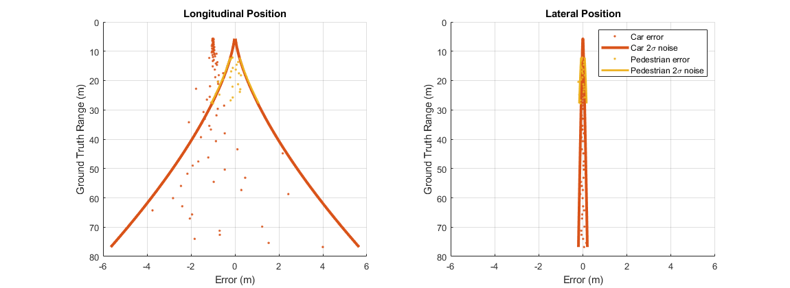
Plot the position errors generated for the target vehicle and pedestrian from the FCW scenario.
helperPlotSensorDemoDetections(metrics, 'position', 'reverse range', [-6 6]);
legend('Car error','Car 2\sigma noise', 'Pedestrian error', 'Pedestrian 2\sigma noise');

The preceding plots show the longitudinal position errors (on the left) and lateral position errors (on the right) generated by the vision sensor's detections of the target vehicle and pedestrian. Errors from detections for the target vehicle (shown in red) are generated out to the farthest range included in this test (75 m), but errors for the pedestrian (shown in yellow) do not appear until the ego vehicle has reached a distance of approximately 30 m. This difference in the detection ranges is due to the difference in the sizes of these two objects.
The sensor stops generating detections from the pedestrian at ranges less than 12 m. At this range, the offset of the pedestrian from the camera's optical axis moves the pedestrian outside of the camera's horizontal field of view. Because the target vehicle is directly in front of the camera, it remains centered within the camera's image for the entire FCW test.
Some vision sensors can detect objects with smaller image sizes, enabling the sensors to detect objects at longer ranges. In the previous scenario, the sensor's detection of the pedestrian is limited by the pedestrian's width (0.45 m), which is much narrower than the width of the car (1.8 m). To increase the sensor's detection range for pedestrians to 40 m, compute the width of the pedestrian in the camera's image when it is at 40 m.
Find physical width modeled for a pedestrian
profiles = actorProfiles(scenario);
pedWidth = profiles(3).Width

% Compute width of pedestrian in camera's image in pixels at 40 meters from ego vehicle
cameraRange = 40-visionSensor.SensorLocation(1);
focalLength = visionSensor.Intrinsics.FocalLength(1);
pedImageWidth = focalLength*pedWidth/cameraRange
pedWidth =

    0.4500


pedImageWidth =

    9.4987

At 40 m, the pedestrian has a width of 9.5 pixels in the camera's image. Set the vision sensor's minimum object width to match the pedestrian's width at 40 m.
% Configure sensor to detect pedestrians out to a range of 40 m.
release(visionSensor);
visionSensor.MinObjectImageSize(2) = pedImageWidth
visionSensor =

  visionDetectionGenerator with properties:

               SensorIndex: 1
            UpdateInterval: 0.1000

            SensorLocation: [2.1000 0]
                    Height: 1.1000
                       Yaw: 0
                     Pitch: 1
                      Roll: 0
                Intrinsics: [1×1 cameraIntrinsics]

            DetectorOutput: 'Objects only'
               FieldOfView: [43.6028 33.3985]
                  MaxRange: 150
                  MaxSpeed: 100
       MaxAllowedOcclusion: 0.6000
        MinObjectImageSize: [15 9.4987]

      DetectionProbability: 0.9000
    FalsePositivesPerImage: 0.1000

  Use get to show all properties
Run the scenario again and plot the position errors to show the revised detection ranges for the vehicle and pedestrian.
% Run simulation and collect detections and ground truth for offline
% analysis.
metrics = helperRunSensorDemoScenario(scenario, egoCar, visionSensor);

% Plot position errors for the target vehicle and pedestrian.
helperPlotSensorDemoDetections(metrics, 'position', 'reverse range', [-6 6]);
legend('Car error','Car 2\sigma noise', 'Pedestrian error', 'Pedestrian 2\sigma noise');

The preceding plots show the longitudinal position errors (on the left) and lateral position errors (on the right) for a vision sensor configured to support pedestrian detection out to a range of 40 m. The vehicle (shown in red) is still detected out to the farthest test range, but now detections on the pedestrian (shown in yellow) are generated out to 40 m from the sensor.
Lane Boundary Measurements and Lane Occlusion
The vision detection generator can also be configured to detect lanes. Recreate the two-lane driving scenario with the lead car and passing car to illustrate the accuracy of a vision sensor's lane boundary measurements. This same merging maneuver is used to occlusion of the lane markings.
% Create passing scenario
leadDist = 40;     % m
speed = 50;        % kph
passSpeed = 70;    % kph
mergeFract = 0.55; % Merge 55% into right lane
[scenario, egoCar] = helperCreateSensorDemoScenario('Passing', leadDist, speed, passSpeed, mergeFract);
Configuration of Vision Sensor Lane Boundary Measurements
Configure the vision sensor used in the previous section, and configure it to generate position and velocity estimates from a smoothing filter with a process noise intensity of 5 m/s^2.
% Configure vision sensor to detect both lanes and objects
release(visionSensor);
visionSensor.DetectorOutput = 'lanes and objects';

% Use actor profiles for the passing car scenario
visionSensor.ActorProfiles = actorProfiles(scenario);
Use helperRunSensorDemoScenario to simulate the motion of the ego and target vehicles.
snapTime = 5.9; % Simulation time to take snapshot for publishing
helperRunSensorDemoScenario(scenario, egoCar, visionSensor, snapTime);

As can be seen above, the default detector can see lane boundaries out to 45 meters or so when presented with an unoccluded view. You can change the intrinsics of the detector to observe its effect.
% show camera intrinsics.
visionSensor.Intrinsics
ans =

  cameraIntrinsics with properties:

             FocalLength: [800 800]
          PrincipalPoint: [320 240]
               ImageSize: [480 640]
        RadialDistortion: [0 0]
    TangentialDistortion: [0 0]
                    Skew: 0
                       K: [3×3 double]
% increase the focal length and observe its effect.
release(visionSensor);
visionSensor.Intrinsics = cameraIntrinsics([1200 1200],[320 240],[480 640])

helperRunSensorDemoScenario(scenario, egoCar, visionSensor, snapTime);
visionSensor =

  visionDetectionGenerator with properties:

               SensorIndex: 1
            UpdateInterval: 0.1000

            SensorLocation: [2.1000 0]
                    Height: 1.1000
                       Yaw: 0
                     Pitch: 1
                      Roll: 0
                Intrinsics: [1×1 cameraIntrinsics]

            DetectorOutput: 'Lanes and objects'
               FieldOfView: [29.8628 22.6199]
                  MaxRange: 150
                  MaxSpeed: 100
       MaxAllowedOcclusion: 0.6000
        MinObjectImageSize: [15 9.4987]
          MinLaneImageSize: [20 3]

      DetectionProbability: 0.9000
    FalsePositivesPerImage: 0.1000

  Use get to show all properties

Changing the focal length from 800 pixels to 1200 in both x- and y-directions zooms the camera, enabling it to detect out to further ranges.
Summary
This example demonstrated how to model the output of automotive vision sensors using synthetic detections. In particular, it presented how the visionDetectionGenerator model:
Provides accurate lateral position and velocity measurements over long ranges, but has limited longitudinal accuracy at long ranges
Limits detection according to a target's physical dimensions and a target's occlusion by other objects in the scenario
Includes longitudinal biases for targets located at different elevations than the ego vehicle
Adjusts object and lane detections due to monocular camera intrinsics.