Graphically Manage AUTOSAR Architectural Data
The Architectural Data section of a Simulink® data dictionary enables interfaces, data types, constants, and AUTOSAR-specific data to be authored, managed, and shared between AUTOSAR components and compositions modeled in Simulink. The Architectural Data section provides scalability for system-level and multicomponent designs by containing these shared elements in a central location. The Architectural Data section also allows you to view and configure AUTOSAR platform properties of interfaces, datatypes, and constants.
You can configure architectural data and apply your changes to a model using this basic workflow:
Create a data dictionary.
Design interface, data types, and constants with the Architectural Data Editor.
Link the data dictionary containing architectural data to a Simulink or architecture model.
Consume architectural data from the Architectural Data section of a Simulink data dictionary linked to a model, in one of these ways:
Assign interfaces to ports in the architecture canvas by using the Interface Editor (System Composer).
Set the data type of ports in the Simulink canvas to an interface or data type stored in the Architectural Data section.
When configuring data intended for the AUTOSAR Classic platform you define property information of port interfaces and elements by using the Architectural Data section. You define platform-specific properties of port interfaces by using architectural data; properties like the kind of interface, whether or not it defines a service, and where it is stored in generated code. For port interface elements, you define other platform-specific properties, like calibration properties and software address methods (an AUTOSAR-specific memory section). This property information and customization is not used by Simulink, but is necessary for workflows involving ARXML code generation.
The following is an example of ways you can configure and customize data of the AUTOSAR Classic platform. Architectural Data is not limited to the AUTOSAR platform, and you can define properties for your architectural data based on your own custom platforms.
Manage software address methods and XML code generation options.
The AUTOSAR Classic platform mapping of an Architectural Data section allows authoring of software address methods in data dictionaries. You use the Architectural Data editor to define software address methods, and apply them to elements in the dictionary or linked model.
Share platform-specific properties across models through data dictionaries.
The Architectural Data section of data dictionaries ensures seamless import and export of data-specific information without explicitly modifying or updating a model.
Export the contents of data dictionaries to ARXML files without creating a model. Standalone authoring of interfaces, data types, constants, and software address methods is only possible using the Architectural Data section of data dictionaries. All UUIDs and AUTOSAR metadata are preserved during export of data dictionaries to ARXML files.
Import interfaces, data types, constants, and software address methods from ARXML files to the Architectural Data section of data dictionaries.
The import of architectural data is supported using the
updateArchitecturalDataandimportFromARXMLfunctions. For an example describing an import workflow of architectural data, see Update Architectural Data Section of Data Dictionary from ARXML.
Create Simulink Data Dictionary and Open Architectural Data Section for Editing
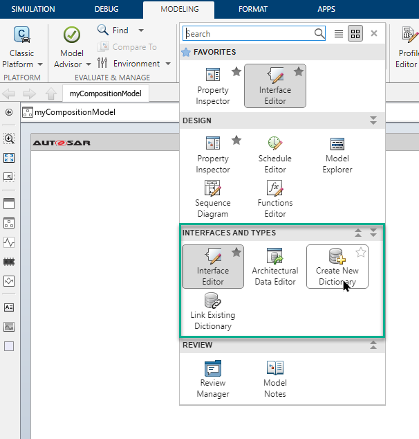
To create a data dictionary from the AUTOSAR architecture model toolstrip, on the Modeling tab, open the Design gallery, and select Create New Dictionary from the Interfaces and Types section.
Design Data Types, Interfaces, and Constants Using Architectural Data Editor
Once you create your data dictionary, you can add and edit architectural data using the Architectural Data Editor. This tool allows you to author elements shared outside of the context of a particular component or composition and allow multiple team members to define and manage these elements.
Open Architectural Data Editor
To open the editor from an AUTOSAR architecture model:
In the Simulink editor of an AUTOSAR architecture model, on the Modeling tab, open the Design gallery and select Architectural Data Editor.
To open the editor from outside the context of a model, use one of these methods:
In the MATLAB® Files panel, navigate to and double-click the
.slddfile to open Model Explorer. Expand the data dictionary file and select Architectural Data, then click Open Architectural Data Editor from the Dialog pane.Use the
showfunction on an Architectural Data object created usingSimulink.dictionary.archdata.createorSimulink.dictionary.archdata.open.Enter
archdataeditorat the MATLAB command line.
Add and Configure Data Using Architectural Data Editor
With the Architectural Data Editor, you can create, configure, and manage architectural data.
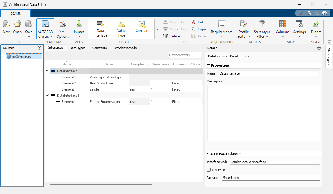
Create — On the toolstrip, in the Create section, add data type definitions, interfaces, and constants. Data types, interfaces, and constants each have a dedicated tab for data management.
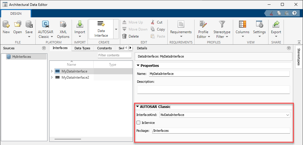
Configure — In the right panel, use the Details pane to configure your data. The Details pane can also display platform-specific properties.
For example, when you set the deployment platform to AUTOSAR Classic, the Details pane displays AUTOSAR interface communication properties such as InterfaceKind, IsService, and Package.
Manage — You can filter, sort, and search data on the Interfaces, Data Types, and Constants tabs.
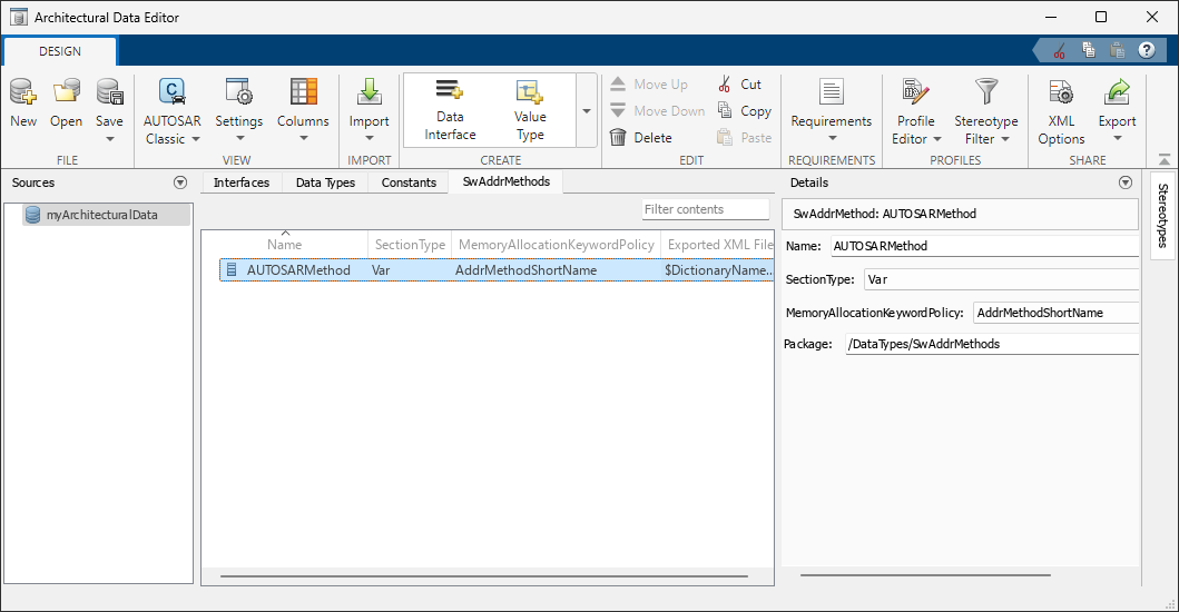
In addition to the Interfaces, Data Types, and Constants tabs, the Architectural Data Editor displays platform-specific software address method data for the AUTOSAR Classic Platform in the SwAddrMethods tab.
Add and Configure Data Using Architectural Data Editor
With the Architectural Data Editor, you can create, configure, and manage architectural data.
Create — On the toolstrip, in the Create section, add data type definitions, interfaces, and constants. Data types, interfaces, and constants each have a dedicated tab for data management.
Configure — In the right panel, use the Details pane to configure your data. The Details pane can also display platform-specific properties.
For example, when you set the deployment platform to AUTOSAR Classic, the Details pane displays AUTOSAR interface communication properties such as InterfaceKind, IsService, and Package.
Manage — You can filter, sort, and search data on the Interfaces, Data Types, and Constants tabs.
In addition to the Interfaces, Data Types, and Constants tabs, the Architectural Data Editor displays platform-specific software address method data for the AUTOSAR Classic Platform in the SwAddrMethods tab.
Link Data Dictionary to Model
To link an existing data dictionary from the AUTOSAR architecture model toolstrip, on the Modeling tab, open the Design gallery and select Link Existing Dictionary from the Interfaces and Types section. When you create a component model from an AUTOSAR architecture model, Simulink automatically links it to the data dictionary.
Consume Architectural Data from Data Dictionaries in Simulink Models
You can consume architectural data in two ways in your model. You can:
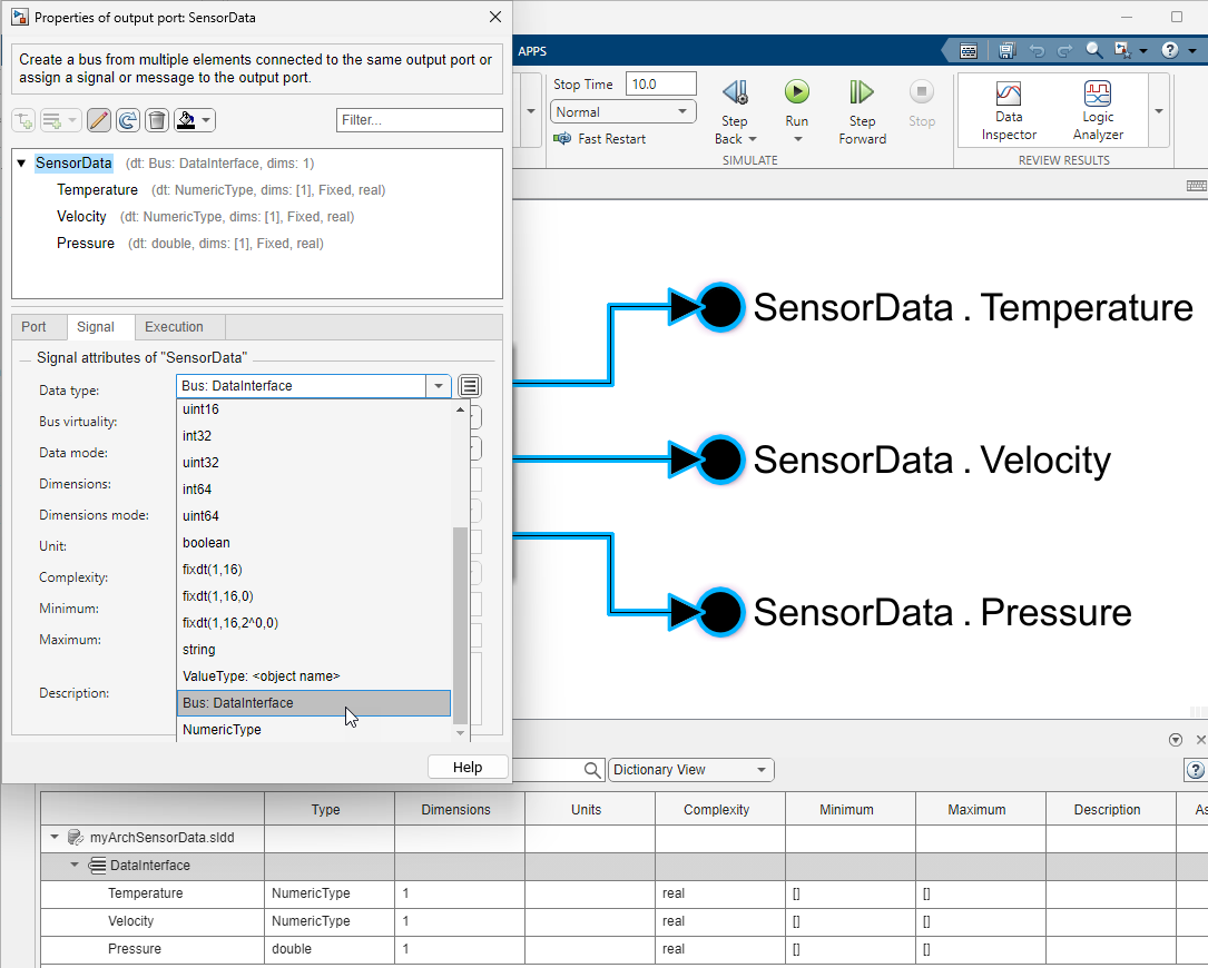
Type ports in a model with architectural data interfaces by editing the signal properties of a port.
Assign architectural data interfaces to ports in an architecture model by using the Interface Editor.
You can type ports with architectural data interfaces by opening the port properties and editing the signal attributes of the port. Set the signal attribute Data type by selecting the architectural data interface from the menu options.
Alternatively, you can consume interfaces in the Architectural Data section of a data dictionary by using the Interface Editor to assign interfaces to ports in an architecture model canvas. In the AUTOSAR model toolstrip, on the Modeling tab, open the Design gallery and select Interface Editor. The editor opens as a pane in the current Simulink editor window.
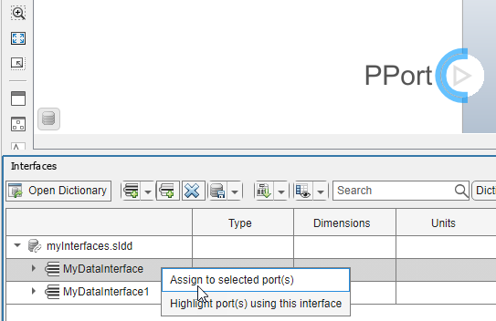
The primary focus of this model-centric editor is applying interfaces to ports. It displays the available interfaces in the linked data dictionary. See Interface Editor (System Composer) for more information.
By using the Interfaces tab you can:
Assign an interface to a selected port on the canvas by right-clicking on the interface.
Trace between ports and interfaces.
Focus on a particular interface by using the Port Interface View.
View and configure a selected interface by using the Property Inspector.
Configure AUTOSAR Classic Platform Properties in Architectural Data Section
View and edit the AUTOSAR Classic Platform properties of architectural data by selecting Architectural Data > AUTOSAR Classic from the View section of the Architectural Data Editor toolstrip. In the AUTOSAR Classic Platform view you can configure platform-specific elements and properties. Specifically, you can:
Define software address methods on the dedicated SwAddrMethods tab.
Configure the AUTOSAR communication kind and calibration properties for data interfaces and interface elements.
Set XML export options.
Export a data dictionary, including architectural data, to ARXML.
To create or view an AUTOSAR Classic Platform mapping for the architectural data in your data dictionary, select Architectural Data > AUTOSAR Classic in the View section of the toolstrip. The toolstrip, the main contents pane, and the Details pane update to display platform-specific options.
To create and configure software address methods:
On the toolstrip, in the Create section, click SwAddrMethod. A software address method definition is added on the SwAddrMethods tab.
Under SwAddrMethods, set SectionType, MemoryAllocationKeywordPolicy, and Exported XML File as needed.
For more information about configuring software address methods, see Configure AUTOSAR SwAddrMethods.
To create and configure data interfaces and data elements:
On the toolstrip, in the Create section, click Data Interface. A data interface object is added under the Interfaces tab.
Under Interfaces, click a data interface and edit its name as needed.
While the interface is selected, configure the attributes of the interface in the main Contents pane and in the Details pane. Platform-specific interface properties InterfaceKind, IsService, and Package are located under the AUTOSAR section in the Details pane.
While the interface is selected, on the toolstrip, in the Create section, click Interface Element to add elements to the interface.
Click a data element and edit its name as needed.
While the data element is selected, configure its attributes in the main Contents pane and in the Details pane.
For Type, supported data types include ones you have created, located on the Data Types tab. See Create and Configure Interface, Data Type, and Constant Definitions for more information.
Platform-specific calibration properties DisplayFormat, SwAddrMethod, SwCalibrationAccess are located under the AUTOSAR section in the Details pane.
To create and configure constants:
On the toolstrip, in the Create section, click Constant. A constant object is added under the Constants tab.
Under the Constants tab, click a constant and edit its name as needed.
While the constant is selected, configure its attributes in the main Contents pane and in the Details pane.
For the Value field, only double data types are supported.
The MappedTo and Package properties are located under the AUTOSAR section in the Details pane.
When you save the Architectural Data section, the interface, data type,
constant, and platform-specific data is saved in the .sldd
file.
For more information about AUTOSAR interface and calibration properties, see
Configure AUTOSAR Communication Interfaces and Configure AUTOSAR Data for Calibration and Measurement. For more information about setting
AUTOSAR properties programmatically, see setPlatformProperty.
Configure AUTOSAR XML Options in Architectural Data Section
To view and edit XML options, on the View tab of the Architectural Data Editor toolstrip, select Architectural Data > AUTOSAR Classic. The XML Options button appears in the Share section of the toolstrip. Component and architecture models linked to the data dictionary use the same XML export parameter values as defined in the linked data dictionary.
On the toolstrip, in the Share section, click the XML Options button to configure the export options. The View and Edit XML Options dialog box for the data dictionary opens.
For more information about XML options for classic architecture modeling, see Configure AUTOSAR XML Options and AUTOSAR XML Options Settings.
Export AUTOSAR Definitions to ARXML and Support Files
You can export AUTOSAR definitions and other architectural data defined in a data dictionary to ARXML.
On the toolstrip, in the Share section, click the
Export button. Data dictionary contents are exported to
ARXML and RTE stub header files are stored in a folder created in the current
working directory. Alternatively, you can use the exportDictionary function to programmatically perform this
operation.
Limitations
Some limitations for AUTOSAR mapped data dictionaries include:
Data dictionary reference hierarchies are not supported for data dictionaries mapped to the AUTOSAR Classic Platform.
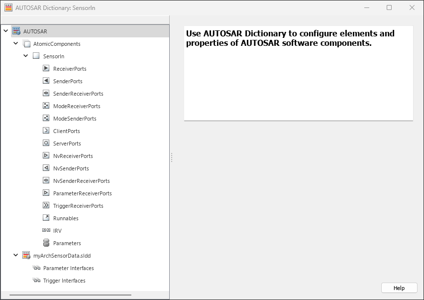
The Interface Editor (System Composer) can only view and edit data interfaces, service interfaces, and value types. To author and view parameter and trigger interfaces for AUTOSAR workflows, use the AUTOSAR Dictionary.
See Also
Tools
Objects
Simulink.dictionary.archdata.AliasType|Simulink.dictionary.archdata.Constant|Simulink.dictionary.archdata.DataInterface|Simulink.dictionary.archdata.DataElement|Simulink.dictionary.archdata.FunctionElement|Simulink.dictionary.archdata.FunctionArgument|Simulink.dictionary.archdata.NumericType|Simulink.dictionary.archdata.PhysicalInterface|Simulink.dictionary.archdata.ServiceInterface|Simulink.dictionary.archdata.StructElement|Simulink.dictionary.archdata.ValueType|Simulink.dictionary.archdata.StructType|autosar.dictionary.ARClassicPlatformMapping
Functions
Simulink.dictionary.archdata.create|Simulink.dictionary.archdata.open|moveToDesignData|moveToDictionary