Main Content

wlanVHTSIGARecover

Recover VHT-SIG-A information bits

Description

example

recBits = wlanVHTSIGARecover(rxSig,chEst,noiseVarEst,cbw) returns the recovered information bits from the VHT-SIG-A1 field. Inputs include the received VHT-SIG-A field, the channel estimate, the noise variance estimate, and the channel bandwidth.

example

recBits = wlanVHTSIGARecover(rxSig,chEst,noiseVarEst,cbw,Name,Value) specifies algorithm parameters by using one or more name-value pair arguments.

[recBits,failCRC] = wlanVHTSIGARecover(___) returns the failure status of the CRC check, failCRC, using the arguments from previous syntaxes.

[recBits,failCRC,eqSym] = wlanVHTSIGARecover(___) returns the equalized symbols, eqSym.

[recBits,failCRC,eqSym,cpe] = wlanVHTSIGARecover(___) returns the common phase error, cpe.

Examples

collapse all

Recover the information bits in the VHT-SIG-A field by performing channel estimation on the L-LTF over a 1x2 quasi-static fading channel

Create a wlanVHTConfig object having a channel bandwidth of 80 MHz. Generate L-LTF and VHT-SIG-A field signals using this object.

cfg = wlanVHTConfig('ChannelBandwidth','CBW80');
txLLTF = wlanLLTF(cfg);
[txVHTSIGA, txBits] = wlanVHTSIGA(cfg);
chanBW = cfg.ChannelBandwidth;
noiseVarEst = 0.1;

Pass the L-LTF and VHT-SIG-A signals through a 1x2 quasi-static fading channel with AWGN.

H = 1/sqrt(2)*complex(randn(1,2),randn(1,2));
rxLLTF    = awgn(txLLTF*H,10);
rxVHTSIGA = awgn(txVHTSIGA*H,10);

Perform channel estimation based on the L-LTF.

demodLLTF = wlanLLTFDemodulate(rxLLTF,chanBW,1);
chanEst = wlanLLTFChannelEstimate(demodLLTF,chanBW);

Recover the VHT-SIG-A. Verify that the CRC check was successful.

[rxBits,failCRC] = wlanVHTSIGARecover(rxVHTSIGA,chanEst,noiseVarEst,'CBW80');
failCRC
failCRC = logical
   0

The CRC failure check returns a 0, indicating that the CRC passed.

Compare the transmitted bits to the received bits. Confirm that the reported CRC result is correct because the output matches the input.

isequal(txBits,rxBits)
ans = logical
   1

Recover the VHT-SIG-A in an AWGN channel. Configure the VHT signal to have a 160 MHz channel bandwidth, one space-time stream, and one receive antenna.

Create a wlanVHTConfig object, specifying a channel bandwidth of 160 MHz.

cfg = wlanVHTConfig('ChannelBandwidth','CBW160');

Generate L-LTF and VHT-SIG-A field signals.

txLLTF = wlanLLTF(cfg);
[txSig,txBits] = wlanVHTSIGA(cfg);
chanBW = cfg.ChannelBandwidth;
noiseVarEst = 0.1;

Pass the transmitted VHT-SIG-A through an AWGN channel.

awgnChan = comm.AWGNChannel('NoiseMethod','Variance','Variance',noiseVarEst);
rxLLTF = awgnChan(txLLTF);
rxSig = awgnChan(txSig);

Perform channel estimation based on the L-LTF.

demodLLTF = wlanLLTFDemodulate(rxLLTF,chanBW,1);
chEst = wlanLLTFChannelEstimate(demodLLTF,chanBW);

Recover the VHT-SIG-A, specifying zero-forcing equalization, and check the CRC result.

[recBits,failCRC] = wlanVHTSIGARecover(rxSig,chEst,noiseVarEst, ...
    'CBW160','EqualizationMethod','ZF');
disp(failCRC)
   0

Verify that the received signal contains no bit errors.

biterr(txBits,recBits)
ans = 0

Configure a 2x2 MIMO VHT channel.

chanBW = 'CBW20';
cfgVHT = wlanVHTConfig('ChannelBandwidth',chanBW, ...
    'NumTransmitAntennas',2,'NumSpaceTimeStreams',2);

Generate L-LTF and VHT-SIG-A waveforms.

txLLTF  = wlanLLTF(cfgVHT);
txVHTSIGA = wlanVHTSIGA(cfgVHT);

Pass the L-LTF and VHT-SIG-A waveforms through the 2×2 MIMO channel with white noise.

mimoChan = comm.MIMOChannel('SampleRate',20e6);
rxLLTF = awgn(mimoChan(txLLTF),15);
rxVHTSIGA = awgn(mimoChan(txVHTSIGA),15);

Demodulate the L-LTF signal. Use the demodulated L-LTF to generate a channel estimate.

demodLLTF = wlanLLTFDemodulate(rxLLTF,chanBW,1);
chanEst = wlanLLTFChannelEstimate(demodLLTF,chanBW);

Recover the information bits in the VHT-SIG-A field.

[recVHTSIGABits,failCRC,eqSym] = wlanVHTSIGARecover(rxVHTSIGA,chanEst,0,chanBW);

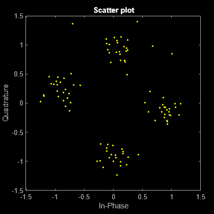
Visualize the scatter plot of the equalized symbols.

scatterplot(eqSym(:))

Input Arguments

collapse all

Received VHT-SIG-A field, specified as an NS-by-NR matrix. NS is the number of samples and increases with channel bandwidth.

Channel BandwidthNS
'CBW20'160
'CBW40'320
'CBW80'640
'CBW160'1280

NR is the number of receive antennas.

Data Types: double | single
Complex Number Support: Yes

Channel estimate, specified as an NST-by-1-by-NR array. NST is the number of occupied subcarriers and increases with channel bandwidth.

Channel BandwidthNST
'CBW20'52
'CBW40'104
'CBW80'208
'CBW160'416

NR is the number of receive antennas.

The channel estimate is based on the L-LTF.

Data Types: double | single
Complex Number Support: Yes

Noise variance estimate, specified as a nonnegative scalar.

Data Types: double | single

Channel bandwidth in MHz, specified as 'CBW20', 'CBW40', 'CBW80', or 'CBW160'.

Data Types: char | string

Name-Value Arguments

Specify optional pairs of arguments as Name1=Value1,...,NameN=ValueN, where Name is the argument name and Value is the corresponding value. Name-value arguments must appear after other arguments, but the order of the pairs does not matter.

Before R2021a, use commas to separate each name and value, and enclose Name in quotes.

Example: 'PilotPhaseTracking','None' disables pilot phase tracking.

OFDM symbol sampling offset represented as a fraction of the cyclic prefix (CP) length, specified as the name-value pair consisting of 'OFDMSymbolOffset' and a scalar in the interval [0, 1]. The value you specify indicates the start location for OFDM demodulation relative to the beginning of the CP. The value 0 represents the start of the CP, and the value 1 represents the end of the CP.

Different values of the OFDMSymbolOffset argument

Data Types: double

Equalization method, specified as one of these values.

  • 'MMSE' — The receiver uses a minimum mean-square error equalizer.

  • 'ZF' — The receiver uses a zero-forcing equalizer.

When the received signal has multiple receive antennas, the function exploits receiver diversity during equalization. When the number of transmitted space-time streams is one and you specify this argument as 'ZF', the function performs maximal-ratio combining.

Data Types: char | string

Pilot phase tracking, specified as the name-value pair consisting of 'PilotPhaseTracking' and one of these values.

  • 'PreEQ' — Enable pilot phase tracking, which the function performs before any equalization operation.

  • 'None' — Disable pilot phase tracking.

Data Types: char | string

Output Arguments

collapse all

Recovered VHT-SIG-A information bits, returned as a 48-by-1 column vector. See VHT-SIG-A for more information.

CRC failure check, returned as true if the CRC check fails or false if the CRC check passes.

Equalized symbols at the data carrying subcarriers, returned as 48-by-2 matrix. Each 20 MHz channel bandwidth segment has two symbols and 48 data carrying subcarriers. These segments are combined into a single 48-by-2 matrix that comprises the VHT-SIG-A field.

Common phase error in radians, returned as a 2-by-1 column vector.

More About

collapse all

VHT-SIG-A

The very high throughput signal A (VHT-SIG-A) field consists of two symbols: VHT-SIG-A1 and VHT-SIG-A2. The VHT-SIG-A field carries information required to interpret VHT PPDU information.

The structure of VHT-SIG-A1

The structure of VHT-SIG-A2

For VHT-SIG-A field bit details, refer to IEEE Std 802.11ac™-2013 [1], Table 22-12.

L-LTF

The L-LTF is the second field in the 802.11™ OFDM PLCP legacy preamble. The L-LTF is a component of EHT, HE, VHT, HT, and non-HT PPDUs.

The L-LTF, second in the legacy preamble

Channel estimation, fine frequency offset estimation, and fine symbol timing offset estimation rely on the L-LTF.

The L-LTF is composed of a cyclic prefix (CP) followed by two identical long training symbols (C1 and C2). The CP consists of the second half of the long training symbol.

The cyclic prefix followed by the two long training symbols in the L-LTF

The L-LTF duration varies with channel bandwidth.

Channel Bandwidth (MHz)Subcarrier Frequency Spacing ΔF (kHz)Fast Fourier Transform (FFT) Period (TFFT = 1 / ΔF)Cyclic Prefix or Training Symbol Guard Interval (GI2) Duration (TGI2 = TFFT / 2)L-LTF Duration (TLONG = TGI2 + 2 × TFFT)
20, 40, 80, 160, and 320312.53.2 μs1.6 μs8 μs
10156.256.4 μs3.2 μs16 μs
578.12512.8 μs6.4 μs32 μs

PPDU

PLCP protocol data unit

The PPDU is the complete PLCP frame, including PLCP headers, MAC headers, the MAC data field, and the MAC and PLCP trailers.

Algorithms

collapse all

VHT-SIG-A Recovery

The VHT-SIG-A field consists of two symbols and resides between the L-SIG field and the VHT-STF portion of the packet structure for the VHT format PPDU.

The structure of a VHT PPDU

For single-user packets, you can recover the length information from the L-SIG and VHT-SIG-A field information. Therefore, it is not strictly required for the receiver to decode the VHT-SIG-A field.

Block diagram of the VHT-SIG-A recovery algorithm

For VHT-SIG-A details, refer to IEEE Std 802.11ac-2013 [1], Section 22.3.4.5, and Perahia [2], Section 7.3.2.1.

References

[1] IEEE Std 802.11ac™-2013 IEEE Standard for Information technology — Telecommunications and information exchange between systems — Local and metropolitan area networks — Specific requirements — Part 11: Wireless LAN Medium Access Control (MAC) and Physical Layer (PHY) Specifications — Amendment 4: Enhancements for Very High Throughput for Operation in Bands below 6 GHz.

[2] Perahia, E., and R. Stacey. Next Generation Wireless LANs: 802.11n and 802.11ac . 2nd Edition, United Kingdom: Cambridge University Press, 2013.

Extended Capabilities

C/C++ Code Generation
Generate C and C++ code using MATLAB® Coder™.

Version History

Introduced in R2015b

expand all


1 IEEE® Std 802.11ac-2013 Adapted and reprinted with permission from IEEE. Copyright IEEE 2013. All rights reserved.