Customize VTOL UAV Configuration
This topic describes the subsystems and supporting files of the VTOL UAV controller template that you can customize.
Getting Started
To open the example live script and the directory that contains the Simulink® project file, first run openExample('uav/CustomizeVTOLConfigurationForYourApplicationExample') in the Command Window.
You must open the VTOLRefApp.prj project file to access the Simulink model, supporting files, and project shortcuts that this example uses.
% Open the Simulink project
prj = openProject("VTOLApp/VTOLRefApp.prj");
To set up the aircraft plant model and base controller, click the Set up Plant button in the project shortcuts or run the setupPlant helper function.
setupPlant
Initialized VTOL model.
Enabled hover configuration.
Enabled hover guidance mission.
The VTOLTiltrotor Simulink model contains these subsystems that enable you to customize the VTOL UAV template:
Ground Control Station— Contains a customized mission, and sends the next state of the mission to the UAV to enable the VTOL UAV to execute a set of maneuvers.Autopilot— The controller for the VTOL aircraft.Digital Twin— The dynamic model of the VTOL, including aerodynamics and propulsion.Visualization— Visualizes the UAV trajectory.
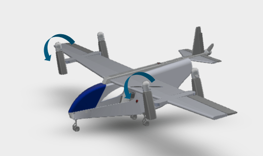
By default, the VTOL UAV controller template models a tilt rotor, where the front rotors can tilt to transition from hover mode to fixed-wing flight.
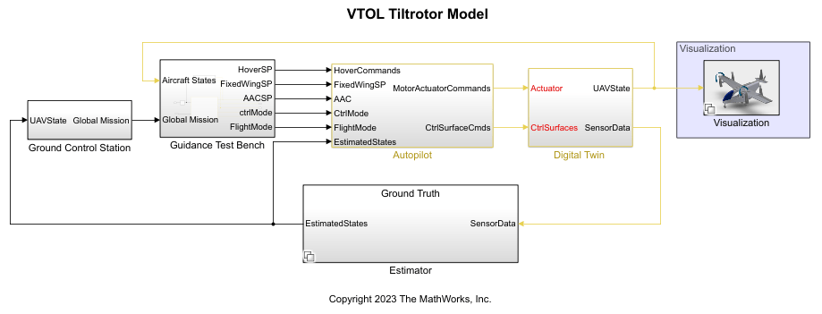
Open the VTOLTiltrotor Simulink model.
open_system("VTOLTiltrotor")Customize VTOL UAV Plant Model
Open the Digital Twin/UAV Dynamics subsystem.
blockpath = Simulink.BlockPath("VTOLTiltrotor/Digital Twin/UAV Dynamics");
open(blockpath)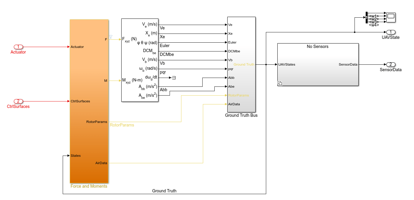
By default, the Digital Twin subsystem models the VTOL UAV in a tilt-rotor configuration. However, you can change the VTOL UAV to a different configuration.
The UAV Dynamics subsystem is a model reference, which references the VTOLDynamics model. The VTOLDynamics model contains the Forces and Moments subsystem, which enables you to customize the dynamics of the VTOL UAV plant model. The Forces and Moments subsystem represents the kinematics of the VTOL UAV by using the 6DOF (Euler Angles) (Aerospace Blockset) block to determine body position, velocity, attitude, and related values.
Open the Forces and Moments subsystem.
blockpath = Simulink.BlockPath(["VTOLTiltrotor/Digital Twin/UAV Dynamics","VTOLDynamics/Force and Moments"]);
open(blockpath)
The Forces and Moments subsystem takes the Actuator and CtrlSurfaces signals as input and produces force and torque that it passes to the 6DOF (Euler Angles) block.
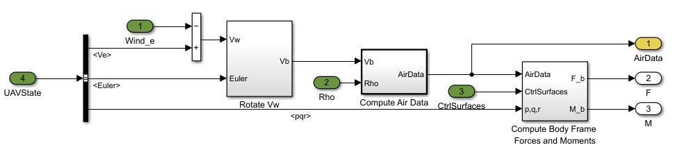
Aerodynamic Forces
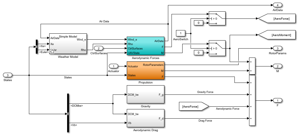
Open the Aerodynamic Forces subsystem.
blockpath = Simulink.BlockPath(["VTOLTiltrotor/Digital Twin/UAV Dynamics", "VTOLDynamics/Force and Moments/Aerodynamic Forces"]);
open(blockpath);
The Compute Air Data subsystem calculates the air data which consists of angle of attack, sideslip angle, airspeed, and dynamic pressure. The Compute Body Frame Forces and Moments subsystem uses the air data, control surface angles, velocity in the body axes, and body angular velocities to calculate the aerodynamic forces in body frame.
Open the Wind frame F& M subsystem which is located inside the Compute Body Frame Forces and Moments subsystem.
blockpath = Simulink.BlockPath(["VTOLTiltrotor/Digital Twin/UAV Dynamics", "VTOLDynamics/Force and Moments/Aerodynamic Forces/Compute Body Frame  Forces and Moments/Wind frame F& M"]);
open(blockpath);
This subsystem calculates the aerodynamic force and moments in the wind frame. You can plug the aerodynamic model of your VTOL UAV into the Lateral Channel and Longitudinal Channel subsystems.
Propulsion
Open the Propulsion subsystem.
blockpath = Simulink.BlockPath(["VTOLTiltrotor/Digital Twin/UAV Dynamics", "VTOLDynamics/Force and Moments/Propulsion"]);
open(blockpath);
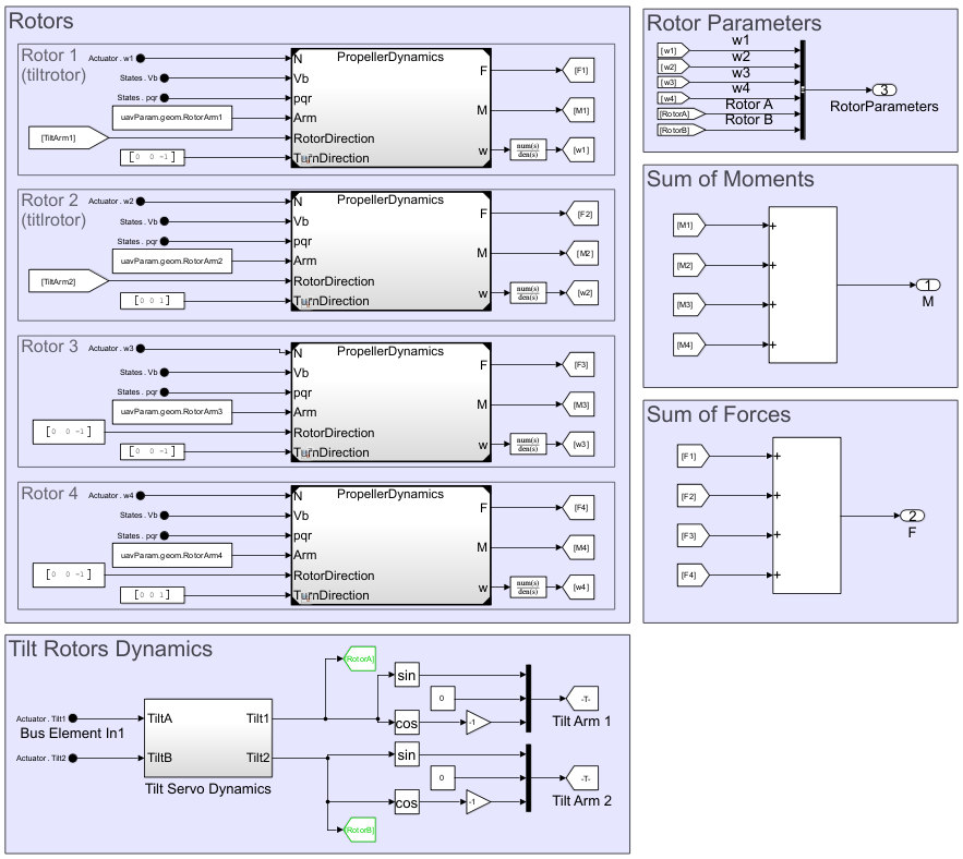
The Propulsion subsystem models the motor, rotor, and tilt dynamics of the VTOL UAV. In this subsystem, each rotor assembly subsystem models the propeller dynamics for the corresponding motor-propeller pair.
By default, the Propulsion subsystem models the UAV in a tilt-rotor configuration, where the front two rotors (in sections Rotor 1 and Rotor 2) can rotate to a vertical position during takeoff or landing, and to a horizontal position during fixed-wing flight.
Wind Model
The Weather Model subsystem of the VTOLTiltrotor.slx allows you to simulate the effect of various wind models on the UAV. You can choose between Simple Model or Weather Model variant subsystem.
Simple Model
Open the Simple Model Model subsystem.
blockpath = Simulink.BlockPath(["VTOLTiltrotor/Digital Twin/UAV Dynamics", "VTOLDynamics/Force and Moments/Weather Model/Weather Model"]);
open(blockpath);
Choose this variant subsystem to simulate the effect of wind with constant magnitude and direction. You can customize the wind magnitude and direction by specifying the input to the Wind_e signal. For example, a value of [10 5 0] corresponds to a wind velocity of 10 m/s, 5 m/s, and 0 m/s in the inertial frame X, Y, and Z direction, respectively.
To select this variant subsystem, run Wind=0 in the Command Window.
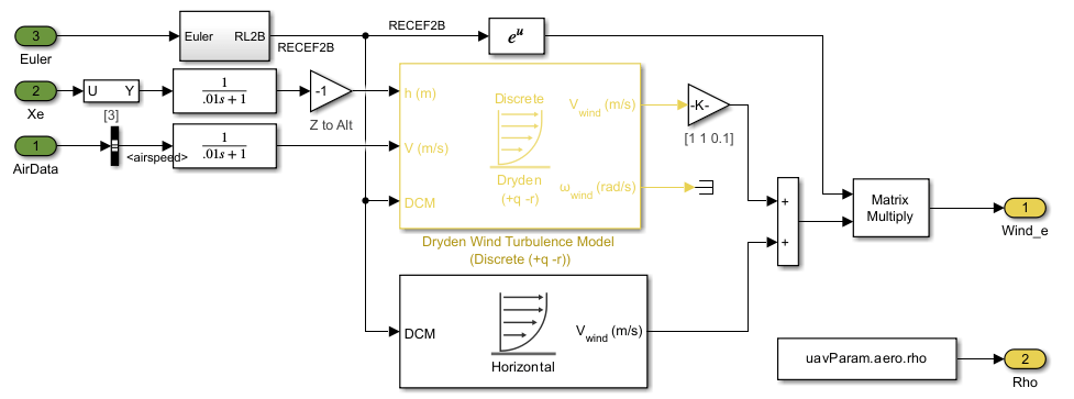
Weather Model
Open the Weather Model subsystem.
blockpath = Simulink.BlockPath(["VTOLTiltrotor/Digital Twin/UAV Dynamics", "VTOLDynamics/Force and Moments/Weather Model/Weather Model"]);
open(blockpath);
Choose this variant subsystem to simulate the effect of wind model with higher complexity. By default, the subsystem uses a combination of Horizontal Wind Model (Aerospace Blockset) and Dryden Wind Turbulence Model (Discrete) (Aerospace Blockset) blocks. You can replace the default wind model blocks with other wind models, such as Discrete Wind Gust Model (Aerospace Blockset), Wind Shear Model (Aerospace Blockset), or implement your own wind model.
To select this variant subsystem, run Wind=1 in the Command Window.
Customize VTOL UAV Control System
After modifying the VTOL UAV plant dynamics, you must also update the control system to accommodate the modified VTOL UAV configuration. To customize the autopilot control system, first examine the layout of the controller in the Autopilot subsystem.
Within the Autopilot subsystem, the Controller subsystem references the VTOLAutopilotController model. Open the Low level controller.
blockpath = Simulink.BlockPath(["VTOLTiltrotor/Autopilot/Controller","VTOLAutopilotController/Low level controller"]);
open(blockpath)
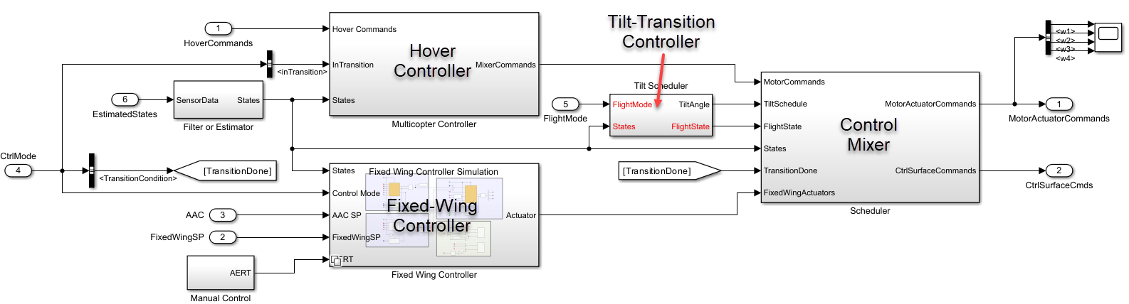
Control Scheduling
You can customize the controller for the VTOL UAV during hover mode by modifying the Multicopter Controller subsystem. Similarly, you can customize the fixed-wing mode controller by modifying the Fixed Wing Controller subsystem. To customize the blending of the two controllers based on the flight state of the VTOL UAV, modify the Scheduler subsystem.
You can modify the tilt transition controller in the Tilt Scheduler subsystem to control the tilt behavior of the front rotors while the VTOL aircraft is in the transition and back transition flight modes.
Flight State Input
The FlightState input signal specifies one of the four distinct flight modes of the VTOL UAV, based on the value of the flightState variable. You can modify the flightState variable by running one of setup helper functions, such as setupHoverConfiguration.
The flight modes and their corresponding flightState values are:
Hover —
0Transition —
1Fixed Wing —
2Back Transition —
3
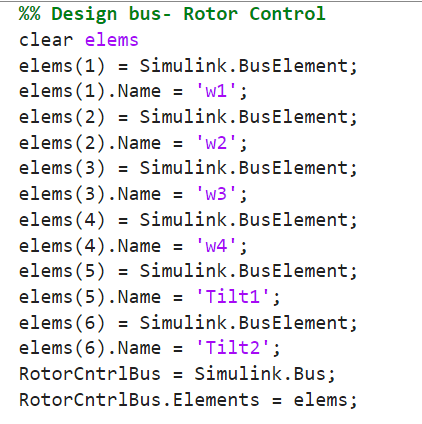
Output Bus Interface
The Digital Twin subsystem receives control output signals grouped together into signal buses. By default, the VTOL UAV uses the rotor control bus and fixed-wing control bus.
The default rotor control bus consists of these signals:
w1— Rotor 1 PWMw2— Rotor 2 PWMw3— Rotor 3 PWMw4— Rotor 4 PWMTilt1— Rotor 1 tilt PWMTilt2— Rotor 2 tilt PWM
The default fixed-wing control bus consists of these signals:
dA— Aileron angle in radiansdE— Elevator angle in radiansdR— Rudder angle in radiansdT— Throttle control for Rotor 1 and Rotor 2 in fixed-wing flight
If you modify the control surface and rotor layout, you must adjust the fixed-wing and rotor control output bus interface accordingly by modifying the exampleHelperDefineDigitalTwinInterface helper file.
To view and modify the exampleHelperDefineDigitalTwinInterface.m helper file, enter this command.
edit("exampleHelperDefineDigitalTwinInterface.m")Customize Flight Mission
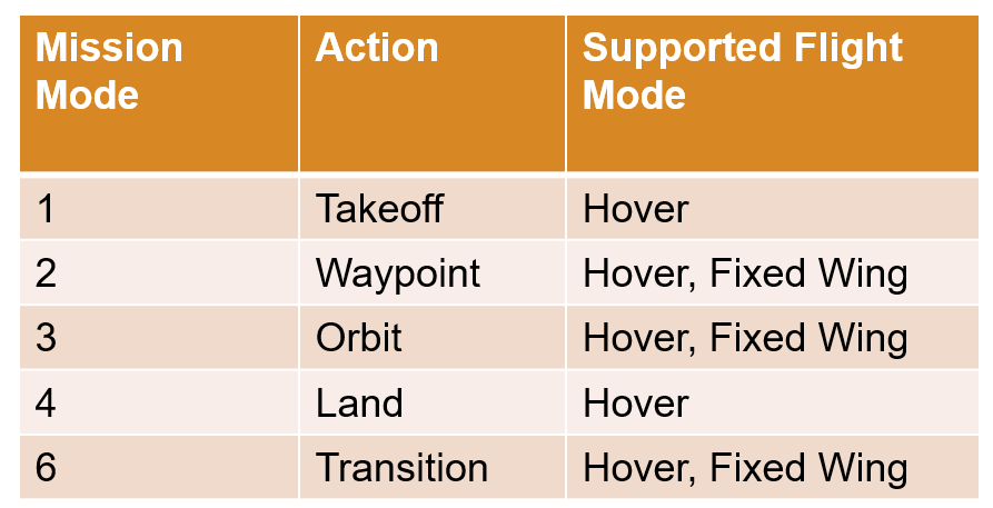
You can customize your flight mission using the supported mission modes of the Path Manager block.
This table lists the mission modes, the associated action for each, and their corresponding VTOL UAV flight modes.
Mode | Action | Supported Flight Mode |
|---|---|---|
1 | Vertical takeoff | Hover |
2 | Waypoint following | Hover, Fixed Wing |
3 | Orbiting waypoint | Hover, Fixed Wing |
4 | Vertical landing | Hover |
6 | Transition between hover and fixed-wing Mode | Hover, Fixed Wing |
Note that mode 5 has been omitted because it corresponds return to launch mode which this model does not use.
You can modify the exampleHelperTransitionMissionData.m helper file to create a new VTOL UAV mission. By default, the helper file contains a mission with these parts:
Takeoff vertically
Hover to two waypoints
Transition to fixed-wing flight mode
Fly to a waypoint
Orbit a waypoint
Transition to hover flight mode
Land vertically
Open the exampleHelperTransitionMissionData.m helper file.
edit('exampleHelperTransitionMissionData.m')Customize VTOL UAV Guidance Logic
Open the Guidance Mode Selector subsystem.
blockpath = Simulink.BlockPath(["VTOLTiltrotor/Autopilot/Controller", ...
    "VTOLAutopilotController/Guidance Test Bench/ControlType/Guidance Testbench/Guidance Logic/Guidance Stateflow/Guidance Mode Selector"]);
open(blockpath);
This stateflow diagram determines the high level control logic that the low level controller uses, and you can plug your custom VTOL UAV guidance logic into this stateflow diagram. This subsystem calculates the setpoint of the low level controller during various flight modes, such as takeoff, forward transition, waypoint navigation, orbit, backward transition, and landing. In addition, the logic determines the conditions in which the modes change during the mission.
For instance, this part of the diagram controls the guidance logic of the UAV before in the pre transition phase.

In this phase, the guidance logic activates the airspeed and altitude controller, the attitude controller, and the course control in fixed-wing mode. It then sets these setpoints for the airspeed, altitude, and course controllers:
L1 distance — 25 meter
Airspeed — 14 m/s
Altitude — present altitude
Course — present course
After 5 seconds, the guidance logic then starts the back transition mode.
Control Modes Output
The Guidance Mode Selector subsystem outputs the ctrlMode bus which contains various flags that is used by the low level controller subsystems. By default, the bus contains these elements:
TransitionCondition— Flag that indicates to the autopilot when it is safe to fully switch to fixed-wing control during forward transition.inTransition— Flag that indicates to the autopilot that the UAV is in transition.lateralGuidance— Flag that activates the fixed wing lateral guidance in the low level controller subsystem.airspeedAltitude— Flag that activates the fixed wing airspeed and altitude guidance in the low level controller subsystem.attitude— Flag that activates the fixed wing attitude guidance in the low level controller subsystem.
Autopilot Setpoints Output
The Guidance Mode Selector subsystem outputs several buses which contains various setpoints for the low level low level controller subsystems. By default, Guidance Mode Selector subsystem outputs these buses:
InnerLoopCmds— X, Y, Z, and yaw angle setpoints.aacSP— Airspeed, altitude, course, L1, climb rate setpoints.FixedWingSP— Roll, pitch, yaw airspeed setpoints.
Guidance Logic Control Interface
If you use a custom guidance logic with a different control mode flags or autopilot setpoint outputs, you must adjust the output bus definitions by modifying the exampleHelperDefineCtrlInterface.m helper file.
To view and modify the exampleHelperDefineCtrlInterface.m helper file, enter this command.
edit("exampleHelperDefineCtrlInterface.m")Customization Example
For an example of how to customize the VTOL UAV controller template to model a different VTOL UAV configuration, see the Model Alternative VTOL UAV Configuration example.
Before resuming to other examples in this example series, you must close the VTOLRefApp.prj Simulink project by running this command in the Command Window:
close(prj)
References
[1] N., Pavan. "Design of Tiltrotor VTOL and Development of Simulink Environment for Flight Simulations." Master's thesis, Indian Institute of Technology Madras, 2020.
[2] Mathur, Akshay, and Ella M. Atkins. "Design, Modeling and Hybrid Control of a QuadPlane." In AIAA Scitech 2021 Forum. VIRTUAL EVENT: American Institute of Aeronautics and Astronautics, 2021. https://doi.org/10.2514/6.2021-0374.
[3] Ducard, Guillaume, and Minh-Duc Hua. "Modeling of an Unmanned Hybrid Aerial Vehicle." In 2014 IEEE Conference on Control Applications (CCA), 1011–16. Juan Les Antibes, France: IEEE, 2014. https://doi.org/10.1109/CCA.2014.6981467.