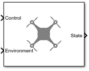
Guidance Model
Reduced-order model for UAV
Libraries:
UAV Toolbox /
Algorithms
Description
Examples
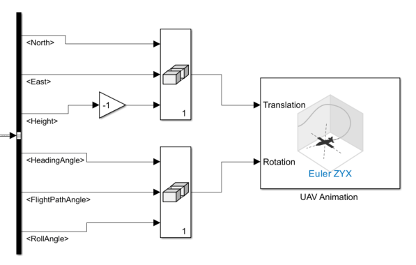
Open the reducedOrderUAVModel.slx Simulink® model. The model uses the Guidance Model block to simulate a UAV with a reduced order fixed-wing kinematic models, and a UAV Animation block to visualize the result.
open_system("reducedOrderUAVModel")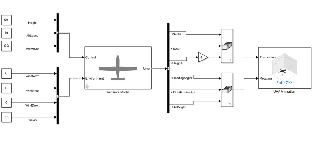
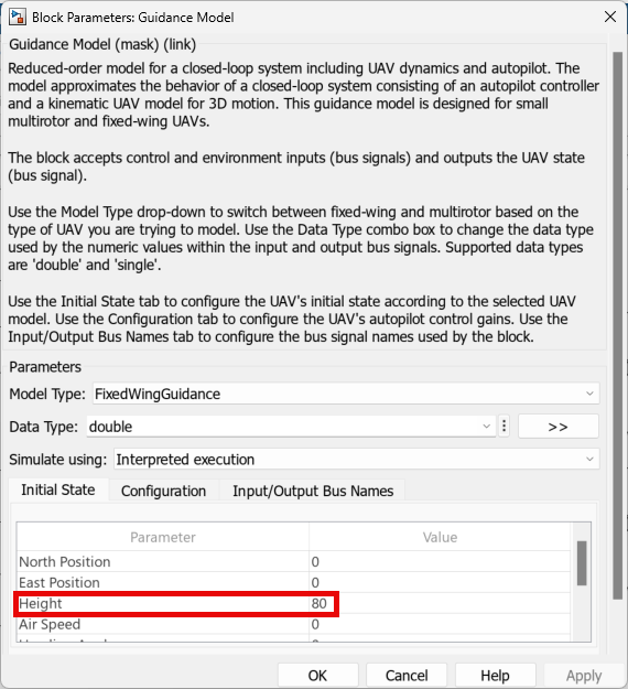
Initial Condition of UAV
This model simulates the flight of a UAV with an initial height of 80 meters. The initial condition is specified in the Initial State parameter of the Guidance Model block.
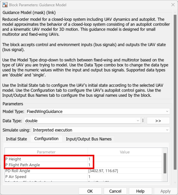
Configuration of UAV
The UAV is configured with a proportional gain of the height controller of 1, and a proportional gain of the flight path angle controller of 1. This configuration is specified in the Configuration parameter of the Guidance Model block.
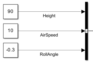
Control Input
This model uses the Bus Creator block to create the control input bus. The bus name is specified in accordance with the Control Bus Name parameter of the Guidance Model block.
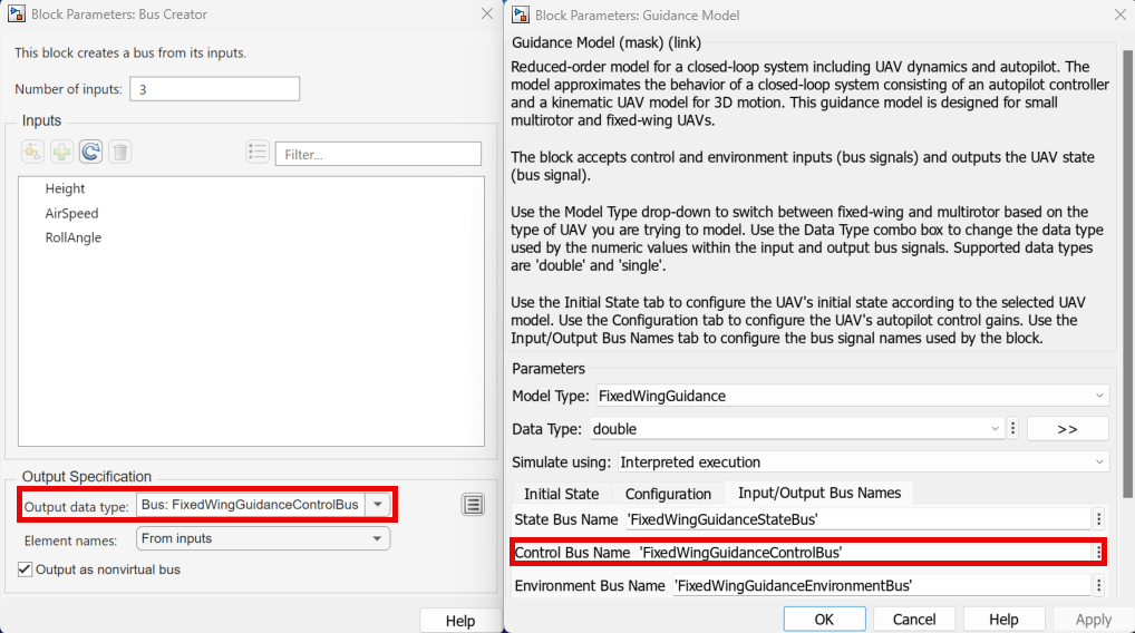
The bus contains these elements:
Height— Sets the UAV to have a height of 90 meters.AirSpeed— Sets the UAV to have an air speed of 10 m/s.RollAngle— Sets the UAV to have a roll angle of -0.3 radians.
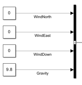
Environment Input
This model uses the Bus Creator block to create the environment input bus. The bus name is specified in accordance with the Environment Bus Name parameter of the Guidance Model block.
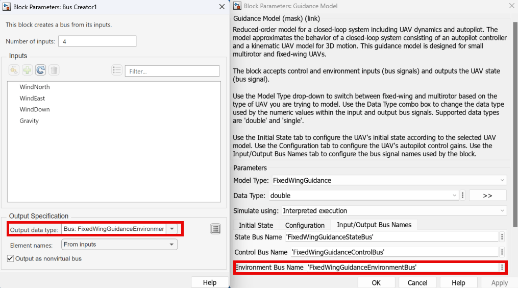
The bus contains the following elements:
WindNorth— Sets the UAV to have north wind velocity of 0 m/s.WindEast— Sets the UAV to have east wind velocity of 0 m/s.WindDown— Sets the UAV to have down wind velocity of 0 m/s.Gravity— Sets the UAV to have a gravitational acceleration of 9.8 m/s2.
Visualizing State Output
Before visualizing the state output, the model performs these operations on the elements of the bus output by the Guidance Model block.
Multiplies the
<Height>signal by a gain of –1 to match the z-axis direction of the UAV Animation block. The model then combine the height signal with<North>and<East>signals into a matrix. The model connects the matrix to the Translation port of the UAV Animation block.Combines the
<HeadingAngle>,<FlightPathAngle>, and<RollAngle>signals into a matrix. The model connects the matrix to the Rotation port of the UAV Animation block.
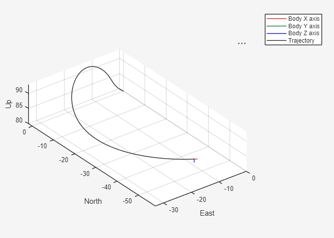
Run the Simulink model, and observe the simulation result from the UAV Animation window.
Ports
Input
Output
Parameters
More About
References
[1] Randal W. Beard and Timothy W. McLain. "Chapter 9." Small Unmanned Aircraft Theory and Practice, NJ: Princeton University Press, 2012.
[2] Mellinger, Daniel, and Nathan Michael. "Trajectory Generation and Control for Precise Aggressive Maneuvers with Quadrotors." The International Journal of Robotics Research. 2012, pp. 664-74.
Extended Capabilities
Version History
Introduced in R2018b