Log, Verify, and Debug Charts
In Stateflow®, you can log data and states to understand when and how they change during simulation. You can add breakpoints to pause execution on states or transitions. By combining these techniques, you can verify and debug your chart logic.
In this example, you identify a design problem in a rechargeable battery model by logging the state activity and data values of a chart. Then, you use breakpoints to identify the state and time step in which the design problem occurs.
Open Model
To build the model, follow the instructions in the previous step of the
tutorial. Alternatively, open the sfGetStartedBattery model
from the MATLAB® command prompt.
In the MATLAB command prompt, enter:
openExample("sfGetStartedBattery")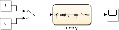
You can charge or discharge the battery by toggling the Manual Switch block.
Double-click the Chart block to enter the Stateflow Editor.

The states
ChargeandDischargerepresent the operating modes of the battery system. The inputisChargingdetermines the active state. The datasentPowerandchargerepresent the output wattage and charge level of the battery.
Log States and Data
The battery system has these requirements:
When
isChargingis true, charge the battery. WhenisChargingis false, discharge the battery.The charge percentage of the battery must remain between 100% and 0%.
Verify the requirements by logging the active state of the chart and the value
of the charge input to the Simulation Data Inspector.
To log the active state of the chart, in the Simulation tab, in the Prepare section, click Log Active State. A logging badge
 appears in the lower-left corner of the
canvas.
appears in the lower-left corner of the
canvas.In the Symbols pane, right-click
chargeand click Inspect. The Property Inspector opens.In the Property Inspector, expand the Logging section and select Log signal data.
Return to the Simulink® Editor.
Right-click the signal line from the Manual Switch block to the chart and click Log Selected Signals.
To simulate the model, in the Simulation tab, click Run. The model simulates until you press Stop.
To transition to the
Dischargestate, double-click the Manual Switch block. Wait several seconds and toggle the Manual Switch block again. Repeat several times. On the final toggle, return the Manual Switch block to0.In the Simulation tab, click Stop to end the simulation.
In the Simulation tab, in the Review Results section, click Data Inspector.
In the Simulation Data Inspector, click Visualization and layouts
 . In the Basic layouts section,
click the
. In the Basic layouts section,
click the 2x1layout .
.To display the active state of the chart, click the top graph. Then, in the Inspect tab, expand the Stateflow section and select
Battery:ActiveChild.To display the output of the Manual Switch block, click the bottom graph. Then, in the Inspect tab, expand the Signals section and select
Manual
                                Switch:1
.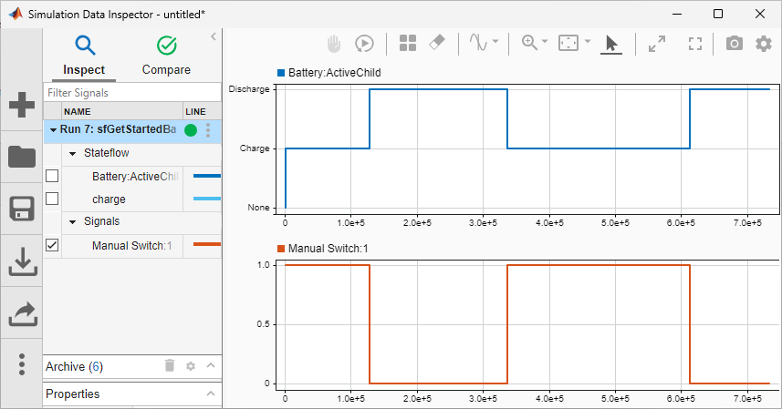
When you toggle the Manual Switch block, the chart transitions between
ChargeandDischargeas expected.To display the value of
charge, click the bottom graph. Then, in the Inspect tab, selectchargeand clearManual Switch:1.
The battery contradicts the requirements by charging above 100% and below 0%.
Set Breakpoints
Set breakpoints on states and transitions to identify the time step in which the design problem occurs.
In the chart, right-click the
Dischargestate and click Set Breakpoint. A red circular breakpoint badge appears on the state. By default, breakpoints on a state trigger when the charts enters or remains in the state.To disable the breakpoint from triggering when the chart enters the state, click the breakpoint badge. In the Discharge Breakpoints dialog box, clear the On State Entry trigger.
Right-click the transition from
ChargetoDischargeand click Set Breakpoint. The breakpoint triggers when the chart moves along the transition.In the Debug tab, click Breakpoints List.
In the Breakpoints List pane, you can enable or disable breakpoints and change the conditions under which they trigger.
Specify that the
Dischargebreakpoint triggers only when the battery charge is negative. In the table row for theDischargestate, double-click the Condition column and entercharge<0.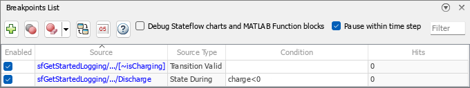
Simulate the model. The simulation pauses on the transition between
ChargeandDischarge.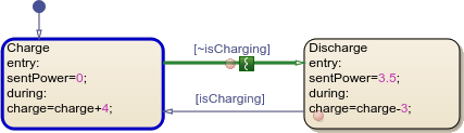
To resume the simulation, in the Simulation tab, click Continue. The simulation pauses on the step when
chargebecomes negative.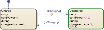
Click Continue again. Because
chargeis still negative, theDischargebreakpoint triggers on the next step.Stop the simulation.
To remove the breakpoints, right-click each breakpoint badge and select Clear Breakpoint.
In the next step of the tutorial, you fix the design problem by adding nested operating modes that slow or stop charging or discharging when the battery reaches certain charge levels.