PWM Generator (Vienna Rectifier)
Vienna rectifier pulse-width modulation waveform generator
Libraries:
Simscape /
Electrical /
Control /
Pulse Width Modulation
Description
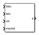
The PWM Generator (Vienna Rectifier) block:
Calculates on-gating and off-gating times based on the block inputs:
Three sinusoidal reference voltages, one per phase, that must be generated at the AC side of the Vienna rectifier, one per phase
Three filtered input sinusoidal current measurements of the Vienna rectifier, one per phase
A DC-link voltage
A DC-link neutral point balance control signal
Uses the gating times to generate three switch-controlling pulses.
The block uses a simplified space vector modulation method based on the equivalence between two-level and three-level converters to generate the control pulses [1].
The three-phase filtered input currents are used to identify the active voltage vector hexagons. The switching sequence selection and on-gating and off-gating times are determined by simplifying the space-vector diagram of a three-level inverter into that of a two-level inverter [2].
The DC link neutral point balance control signal that comes from the external DC link neutral control loop is used to adjust the time distribution of the redundant voltage vectors within one single switching period.
Sampling Mode
The block allows you to choose natural, symmetric, or asymmetric sampling of the modulation wave.
The PWM Generator (Vienna Rectifier) block does not perform carrier-based pulse-width modulation (PWM). Instead, the block uses input signals to calculate gating times and uses the gating times to generate the switch-controlling pulses.
For more information about the sampling modes, see PWM Generator (Three-phase, Two-level).
Examples

Vienna Rectifier Control
Control a Vienna rectifier. The Vienna rectifier subsystem consists of three-phase legs. Each leg has one power switch and six power diodes. The Control subsystem implements a closed-loop control strategy for the Vienna rectifier using space-vector modulation. Total simulation time is 0.1 s. At time 0.1 s, the Vienna Rectifier is engaged. At times 0.4 s and 0.6 s, the load steps up on the DC side.
Ports
Input
Output
Parameters
References
[1] R. Burgos, R. Lai, Y. Pei, F. Wang, D. Boroyevich, and J. Pou, “Space vector modulation for Vienna-type rectifiers based on the equivalence between two- and three-level converters: A carrier-based implementation”, IEEE Trans. Power Electron., vol. 23, no. 4, pp. 1888–1898, Jul. 2008
[2] J. H. Seo, C. H. Choi, and D. S. Hyun, “A new simplified space-vector PWM method for three-level inverters”, IEEE Trans. Power Electron., vol. 16, no. 4, pp. 545–550, Jul. 2001.
Extended Capabilities
Version History
Introduced in R2019b