PWM Generator
Generate pulse width modulated signal or waveform
Libraries:
Simscape /
Electrical /
Control /
Pulse Width Modulation
Description
The PWM Generator block implements a PWM generator. The pulse width modulation technique controls power transfer from one electrical component to another by quickly switching between full power transfer and no power transfer.
Working Principle
The PWM generator block outputs either 1 when the duty cycle is
greater than the carrier counter value, or 0 otherwise. You can
set the period of each cycle by specifying the timer period Tper.
You can change the initial output, or phase, of the PWM output by specifying one of
three types of carrier counters:
Up counter — The PWM output signal initializes at the start of the
oncycle. This graphic shows the carrier counter signal and the corresponding PWM output.
Down counter — The PWM output signal initializes at the start of the
offcycle. This graphic shows the carrier counter signal and the corresponding PWM output.
Up-down counter — The PWM output signal initializes halfway through the
oncycle. This graphic shows the carrier counter signal and the corresponding PWM output.
Examples

DC Motor Control
A cascade speed-control structure for a DC motor. A PWM controlled four-quadrant Chopper is used to feed the DC motor. The Control subsystem includes the outer speed-control loop, the inner current-control loop, and the PWM generation. The total simulation time (t) is 4 seconds. At t = 1.5 seconds, the load torque increases. At t = 2.5 seconds, the reference speed is changed from 1000 rpm to 2000 rpm.
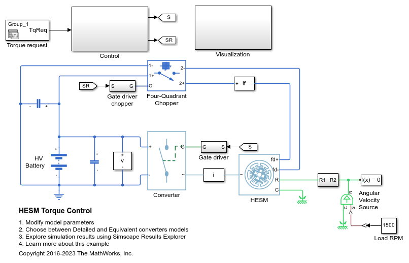
HESM Torque Control
Control the torque in a hybrid excitation synchronous machine (HESM) based electrical-traction drive. Permanent magnets and an excitation winding excite the HESM. A high-voltage battery feeds the SM through a controlled three-phase converter for the stator windings and through a controlled four quadrant chopper for the rotor winding. An ideal angular velocity source provides the load. The Control subsystem uses an open-loop approach to control the torque and a closed-loop approach to control the current. At each sample instant, the torque request is converted to relevant current references. The current control is PI-based. The simulation uses several torque steps in both the motor and generator modes. The Visualization subsystem contains scopes that allow you to see the simulation results.
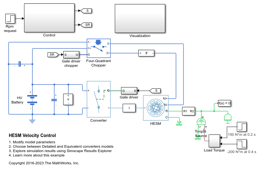
HESM Velocity Control
Control the rotor angular velocity in a hybrid excitation synchronous machine (HESM) based electrical-traction drive. Permanent magnets and an excitation winding excite the HESM. A high-voltage battery feeds the HESM through a controlled three-phase converter for the stator windings and through a controlled four quadrant chopper for the rotor winding. An ideal torque source provides the load. The Control subsystem includes a multi-rate PI-based cascade control structure. The control structure has an outer angular-velocity-control loop and three inner current-control loops. The Visualization subsystem contains scopes that allow you to see the simulation results.
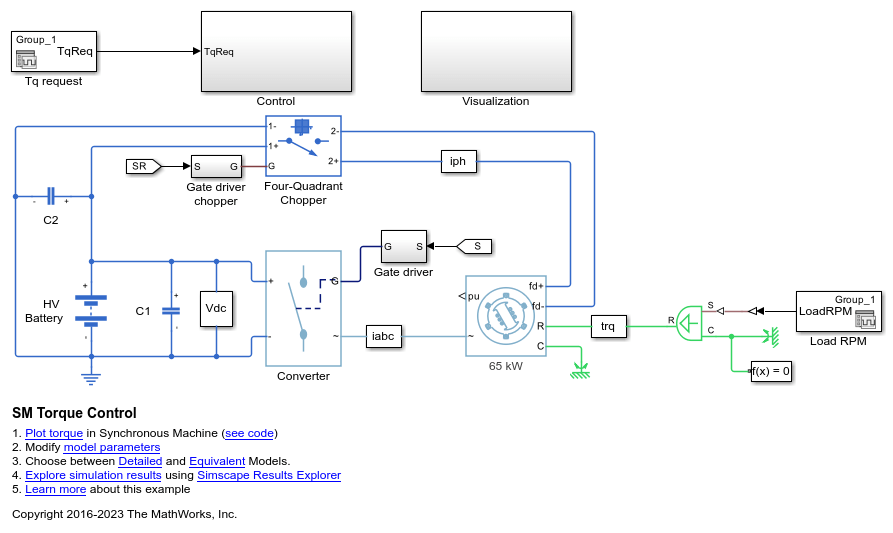
SM Torque Control
Control the torque in a synchronous machine (SM) based electrical-traction drive. A high-voltage battery feeds the SM through a controlled three-phase converter for the stator windings and a controlled four quadrant chopper for the rotor winding. An ideal angular velocity source provides the load. The Control subsystem uses an open-loop approach to control the torque and a closed-loop approach to control the current. At each sample instant, the torque request is converted to relevant current references. The current control is PI-based. The simulation uses several torque steps in both motor and generator modes. The task scheduling is implemented as a Stateflow® state machine. The Visualization subsystem contains scopes that allow you to see the simulation results.
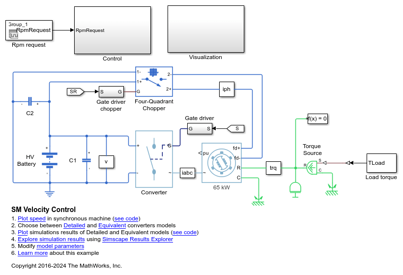
SM Velocity Control
Control the rotor angular velocity in a synchronous machine (SM) based electrical-traction drive. A high-voltage battery feeds the SM through a controlled three-phase converter for the stator windings and a controlled four quadrant chopper for the rotor winding. An ideal torque source provides the load. The Control subsystem includes a multi-rate PI-based cascade control structure which has an outer angular-velocity-control loop and three inner current-control loops. The task scheduling in the Control subsystem is implemented as a Stateflow® state machine. The Visualization subsystem contains scopes that allow you to see the simulation results.
Ports
Input
Output
Parameters
Extended Capabilities
Version History
Introduced in R2017b