Reduced Order Flexible Solid
Create flexible body using reduced-order model data
Libraries:
Simscape /
Multibody /
Body Elements /
Flexible Bodies
Description
The Reduced Order Flexible Solid block creates a flexible body by using reduced-order model (ROM) data.
A reduced-order model is a computationally efficient model that characterizes the properties of a flexible body that can have linear elastic deformations. The ROM data must include:
Coordinates and unit quaternions that specify the positions and orientations of all interface frames relative to a common reference frame. See Interface Frames.
A symmetric stiffness matrix that describes the elastic properties of the flexible body. See Stiffness Matrix.
A symmetric mass matrix that describes the inertial properties of the flexible body. See Mass Matrix.
To generate ROM data, you can use the Flexible Body Model Builder app or finite-element analysis tools, such as the Partial Differential Equation Toolbox™. By using the toolbox, you can start with the CAD geometry of the body, generate a finite-element mesh, apply the Craig-Bampton method, and generate the corresponding ROM data. For more information, see Model an Excavator Dipper Arm as a Flexible Body.
Common Reference Frame
The data provided to the Reduced Order Flexible Solid block must refer to a consistent common reference frame. This reference frame defines the x, y, and z directions that specify the relative position of all points in the body. The frame also defines the directions of the elastic degrees of freedom associated with each interface frame.
Requirements for the ROM Data
The ROM data for the Reduced Order Flexible Solid block must satisfy these requirements:
The ROM data must have at least one boundary node. Each boundary node determines the location of an interface frame.
Each boundary node must contribute six degrees of freedom to the reduced-order model. The degrees of freedom for node i must be retained in the order
Ui = [Txi, Tyi, Tzi, Rxi, Ryi, Rzi],
where:
Txi, Tyi, and Tzi are translational degrees of freedom along the x, y, and z directions of the common reference frame.
Rxi, Ryi, and Rzi are rotational degrees of freedom about the x, y, and z axes of the common reference frame.
The reduced-order model can also include additional degrees of freedom, D1, D2, ⋯, Dm, that correspond to retained normal vibration modes. For a reduced-order model that has n boundary nodes and m modal degrees of freedom, the degrees of the freedom of the model is:
Ureduced
= [U1,
U2, ⋯,
Un,
D1,
D2, ⋯,
Dm].
The number of the degrees of freedom
Nreduced
equals 6n + m, which includes six rigid-body degrees of freedom. The number of
elastic degrees of freedom equals
Nreduced
- 6. The number of the degrees of freedom determines the size of the stiffness and
mass matrices. For the matrices, the order of the rows and columns must correspond
to the order of the
Ureduced.
Reduce the Degrees of Freedom for a Flexible Body
You can use the block to further reduce the degrees of freedom for a flexible body. The fewer the degrees of freedom for flexible bodies, the faster the simulation.
For example, a ROM data set generated by the Craig-Bampton method with two
boundary nodes and 10 fixed-interface normal modes has a total of 22 degrees of
freedom. If you use the ROM data, the block generates an internal representation of
the flexible body that has six rigid-body and 16 elastic degrees of freedom. To
further reduce the number of the elastic degrees of freedom, you can set
Reduction to Modally Reduced. If
you specify Number of Retained Modes to 8,
the flexible body retains the eight lowest-frequency modal degrees of freedom in
addition to the six rigid-body degrees of freedom.
Damping
To specify the damping characteristics of the flexible bodies, the block has three damping methods: proportional damping, uniform modal damping, and damping matrix methods. For more informations, see Damping.
Simulation Performance
Flexible bodies can increase the numerical stiffness of a multibody model. To
avoid simulation issues, use a stiff solver such as ode15s or
ode23t.
Damping can significantly influence simulation performance. For example, when modeling a body with little or no damping, undesirable high-frequency modes in the response can slow the simulation. In that case, adding a small amount of damping can improve the speed of the simulation without significantly affecting the accuracy of the model.
Examples
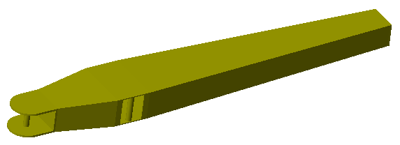
Model an Excavator Dipper Arm as a Flexible Body
Use the Reduced Order Flexible Solid block to model a deformable body of arbitrary geometry. Start with the CAD geometry of the body, produce a finite-element mesh, and generate reduced-order data to use with the block.
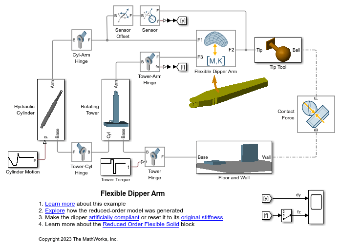
Using the Reduced Order Flexible Solid Block - Flexible Dipper Arm
Model a flexible dipper arm, such as the arm for an excavator or a backhoe, by using the Reduced Order Flexible Solid block. This block captures the mechanical behavior of a deformable body through reduced-order stiffness and mass matrices that are associated with interface frame locations. In this example, the Partial Differential Equation Toolbox™ is used to create the reduced-order model.
Ports
Frame
Output
Parameters
Unit System
System of units in which to express length, mass, time, and other derived units of measure used in all block parameters. Angle measure is always in radians.
| Unit System | Base Units | Selected Derived Units | ||||
|---|---|---|---|---|---|---|
| Length | Mass | Time | Force | Stress and Pressure | Density | |
SI | m | kg | s | N = kg·m/s2 | Pa = kg/(m·s2) | kg/m3 |
CGS | cm | g | s | dyn = g·cm/s2 | Ba = g/(cm·s2) | g/cm3 |
English | ft | slug | s | lbf = slug·ft/s2 | slug/(ft·s2) | slug/ft3 |
To specify units of length, mass, and time individually, select
Custom. For example, suppose that you
specify a custom unit system with mm for
length, t for mass, and
s for time. The derived units include N = t·mm/s2 for force, MPa = t/(mm·s2) for stress and pressure, and t/mm3 for density.
Note
The specified units must be consistent with the imported data. For
example, you must set the Unit System parameter
to SI (m, kg, s) when using the ROM data
generated by the Flexible Body Model Builder app because the generated ROM
data use SI units.
Unit of measure in which to express length.
Dependencies
To enable this parameter, set Unit System to
Custom.
Unit of measure in which to express mass.
Dependencies
To enable this parameter, set Unit System to
Custom.
Unit of measure in which to express time.
Dependencies
To enable this parameter, set Unit System to
Custom.
Interface Frames
Number of interface frame ports, specified as a positive integer. This number must match the number of boundary nodes defined in the ROM data. The parameter does not support variables or expressions.
Cartesian coordinates of all interface frame origins, specified as a n-by-3 matrix. Each row of the matrix represents one frame origin. All coordinates must be relative to the common reference frame. Each boundary node in the reduced-order model must have a corresponding interface frame on the block.
Orientations of interface frames, specified as an n-by-4 matrix of unit quaternions, where n is the number of interface frames.
Reduced Order Matrices
Stiffness matrix from the ROM data, specified as a r-by-r matrix. The stiffness matrix is a symmetric matrix that describes the elastic properties of the flexible body. For a ROM data set with n boundary nodes and m dynamic deformation modes, the stiffness matrix has r = 6n + m rows and columns.
Mass matrix from the ROM data, specified as a r-by-r matrix. The mass matrix is a symmetric matrix that describes the inertial properties of the flexible body. For a ROM data set with n boundary nodes and m dynamic deformation modes, the mass matrix has r = 6n + m rows and columns.
Damping
Damping method to apply to the flexible body:
Select
Proportionalto apply the proportional (or Rayleigh) damping method. This method defines the damping matrix [C] as a linear combination of the mass matrix [M] and stiffness matrix [K]:,
where α and β are scalar coefficients.
Select
Uniform Modalto apply the uniform modal damping method. This method applies a single damping ratio to all the vibration modes of the solid. The larger the value, the faster vibrations decay.The chosen reference conditions impact the types of modes to which the damping ratio applies. For details on reference conditions, see Reference Conditions. When you use modal reduction for the flexible body, only a subset of modes is retained. For details on modal reduction, see Reduce the Degrees of Freedom for a Flexible Body.
Select
Damping Matrixto use a reduced-order damping matrix that you computed with the stiffness and mass matrices. For example, you can use this option to specify a modal damping model for the flexible body.Select
Noneto model undamped body.
Coefficient, α, of the mass matrix. This parameter defines damping proportional to the mass matrix [M].
Dependencies
To enable this parameter, set Type to
Proportional.
Coefficient, β, of the stiffness matrix. This parameter defines damping proportional to the stiffness matrix [K].
Dependencies
To enable this parameter, set Type to
Proportional.
Damping ratio, ζ, applied to all vibration modes of the flexible body. The larger the value, the faster the vibrations decay.
When ζ = 0, the body is undamped. If the boundary conditions applied to the body exactly match the chosen reference conditions, ζ < 1 yields underdamped modal decay, ζ = 1 corresponds to critical damping, and ζ > 1 yields overdamped dissipation. When the boundary conditions and reference conditions do not match, the effect of the chosen damping ratio varies. For details of reference condition, see Reference Conditions.
Dependencies
To enable this parameter, set Type to
Uniform Modal.
Data Types: double
Reduced-order damping matrix, specified as a r-by-r matrix. The damping matrix is a symmetric matrix that describes the damping properties of the flexible body. In a flexible body with n boundary nodes and m dynamic deformation modes, the damping matrix has r = 6n + m rows and columns.
Dependencies
To enable this parameter, set Type to
Damping Matrix.
Reference Conditions
Specify the type of reference conditions to apply. For details, see Reference Conditions.
Linearized Mean Axes: The body frame of reference follows the instantaneous center of mass and the flexible body exhibits unconstrained vibration modes of deformation.Body-Fixed: Choose a body-attached frame as the body frame of reference. The deformation of the flexible body exhibits free vibration mode shapes with zero translational and rotational deformation at the location of the body frame of reference.
Enter the name of the connection frame to use as the body frame of reference. The frame name is case-sensitive. Ensure the selected frame is exposed as a port on the block. You cannot use the R frame, which is the reference frame of the fictitious undeformed body.
Dependencies
To enable this parameter, set Type to
Body-Fixed.
Select to expose the R port, which represents the reference frame of the fictitious undeformed body. Note that the R frame is not physically attached to the flexible body.
The R port must not be rigidly connected to any blocks that exert forces and torques or possess inertia.
Fidelity
Method to use to model flexible bodies, specified as
None or Modally
Reduced.
If you select
None, the block models a flexible body with all the degrees of freedom.If you select
Modally Reduced, the block performs an eigenvalue decomposition to the mass and stiffness matrices of the flexible body. You can then use the Number of Retained Modes parameter to specify the desired normal modes of the flexible body for the simulation.
Retained normal modes, specified as an integer in range [0, n], where n equals the number of elastic degrees of freedom of the flexible body.
The block uses this parameter to specify how many low-frequency modes
to retain for the simulation. If you set this parameter to
0, the flexible body is treated as a rigid body.
The larger the number, the slower the simulation.
Dependencies
To enable this parameter, set Type to
Modally Reduced.
Graphic
Visual representation of the flexible body, specified as
None, Partitioned
Geometry, or Deformed
Geometry.
To hide the body, use
None.To show the deformed body by using an approximate representation that consists of several rigid pieces, use
Partitioned Geometry. In the visualization, the block divides the body into several pieces according to the interface frames and rigidly attaches each piece to its corresponding interface frame.To show the reconstructed deformed shape of the body, use
Deformed
                                Geometry
. The block uses the provided triangulation of the body and the recovery data to reconstruct the elastic deformations of the vertices on the triangulation.
CAD file name or path to CAD file, specified as a character vector. If the file name or path does not include a file extension, the block assumes the file type is STEP. The block supports various formats of CAD files. For a list of supported CAD file formats, see Supported Software and File Formats.
Depending on the location of the CAD file, use one of these methods to specify File Name.
| Location | Methods |
|---|---|
| File is in the current working folder or on the MATLAB® path | Enter the file name in the text box. Example:
|
| File is in a folder that is neither the current folder nor on the MATLAB path |
|
Tip
When using the block across multiple platforms or sharing the model with others, consider using either the file name or relative path.
A forward slash (/) is a valid separator on any platform. A backward slash (\) is valid only on Microsoft Windows platforms.
Source of the solid geometry unit, specified as From
File or From Unit System.
Select From File to use the units specified
in the imported file. Select From Unit System
to use the units specified by the Unit System
parameter.
Dependencies
To enable this parameter, set Type to
Partitioned Geometry.
Coordinates of the vertices on the triangulation representation for the solid, specified as a nv-by-3 matrix. nv is the number of vertices, and each row of the matrix contains the x, y, and z coordinates for a vertex. The coordinates refer to the common reference frame.
Dependencies
To enable this parameter, set Type to
Deformed Geometry.
Indices of vertices that define the facets of the triangulation representation for the solid, specified as a nf-by-3 matrix. nf is the number of facets, and each row of the matrix contains the indices of three vertices that define their corresponding facet. The index of a vertex is the row number of the vertex in the matrix for the Vertex Coordinates parameter.
Dependencies
To enable this parameter, set Type to
Deformed Geometry.
Recovery data to visualize the deformed body, specified as a 3nv-by-r matrix. nv is the number of vertices and r is the number of columns of the mass or stiffness matrix in the ROM data.
The Reduced Order Flexible Solid block uses the reconstruction matrix to calculate the displacements of the vertices on the triangulation representation to display the deformed shape of the body. Each set of three rows of the matrix corresponds to the x, y, and z displacements of a vertex.
Dependencies
To enable this parameter, set Type to
Deformed Geometry.
Parameterization for specifying visual properties.
Select
From Fileto use color data from the imported CAD geometry file. Note that not all file formats allow color data. In formats that allow color data, that data is often optional. If your file does not specify color, the solid is rendered in gray.Select
Simpleto specify Color and Opacity.Select
Advancedto specify more visual properties, such as Diffuse Color, Specular Color, Ambient Color, Emissive Color, and Shininess.
Dependencies
To enable this parameter, set Type to
Partitioned
                                            Geometry
.
Color of the graphic under direct white light, specified as an [R G B] or [R G B A] vector on a 0–1 scale. An optional fourth element (A) specifies the color opacity on a scale of 0–1. Omitting the opacity element is equivalent to specifying a value of 1.
Dependencies
To enable this parameter, set:
Type to
Partitioned Geometry.Visual Properties to
Simple.
Graphic opacity, specified as a scalar in the range of 0 to 1. A scalar of 0 corresponds to completely transparent, and a scalar of 1 corresponds to completely opaque.
Dependencies
To enable this parameter, set:
Type to
Partitioned Geometry.Visual Properties to
Simple.
Color of the light due to diffuse reflection, specified as an [R,G,B] or [R,G,B,A] vector with values in the range of 0 to 1. The vector can be a row or column vector. The optional fourth element specifies the color opacity. Omitting the opacity element is equivalent to specifying a value of 1.
The diffuse color reflects the main color of the rendered solid and provides shading that gives the rendered object a three-dimensional appearance.
Dependencies
To enable this parameter, set:
Type to
Partitioned Geometry.Visual Properties to
Advanced.
Color of the light due to specular reflection, specified as an [R,G,B] or [R,G,B,A] vector with values in the range of 0 to 1. The vector can be a row or column vector. The optional fourth element specifies the color opacity. Omitting the opacity element is equivalent to specifying a value of 1. This parameter changes the color of the specular highlight, which is the bright spot on the rendered solid due to the reflection of the light from the light source.
Dependencies
To enable this parameter, set:
Type to
Partitioned Geometry.Visual Properties to
Advanced.
Color of the ambient light, specified as an [R,G,B] or [R,G,B,A] vector with values in the range of 0 to 1. The vector can be a row or column vector. The optional fourth element specifies the color opacity. Omitting the opacity element is equivalent to specifying a value of 1.
Ambient light refers to a general level of illumination that does not come directly from a light source. The Ambient light consists of light that has been reflected and re-reflected so many times that it is no longer coming from any particular direction. You can adjust this parameter to change the shadow color of the rendered solid.
Dependencies
To enable this parameter, set:
Type to
Partitioned Geometry.Visual Properties to
Advanced.
Color due to self illumination, specified as an [R,G,B] or [R,G,B,A] vector in the range of 0 to 1. The vector can be a row or column vector. The optional fourth element specifies the color opacity. Omitting the opacity element is equivalent to specifying a value of 1.
The emission color is color that does not come from any external source, and therefore seems to be emitted by the solid itself. When a solid has an emissive color, the solid can be seen even if there is no external light source.
Dependencies
To enable this parameter, set:
Type to
Partitioned Geometry.Visual Properties to
Advanced.
Shininess of the rendered solid, specified as a scalar in the range of 0 to 128. This parameter affects the sharpness of the specular reflections of the rendered solid. A solid with high shininess has a mirror-like appearance, and a solid with low shininess has a more low-gloss or satin appearance.
Dependencies
To enable this parameter, set:
Type to
Partitioned Geometry.Visual Properties to
Advanced.
References
[1] Shabana, Ahmed A. Dynamics of Multibody Systems. Fourth edition. New York: Cambridge University Press, 2014.
[2] Agrawal, Om P., and Ahmed A. Shabana. “Dynamic Analysis of Multibody Systems Using Component Modes.” Computers & Structures 21, no. 6 (January 1985): 1303–12. https://doi.org/10.1016/0045-7949(85)90184-1.