Constant Velocity Joint
Joint that enforces a constant-velocity kinematic constraint between two shafts
Libraries:
Simscape /
Multibody /
Joints
Description
The Constant Velocity Joint block enforces a constant-velocity (CV) kinematic constraint between its base and follower frames, whose origins are coincident throughout the simulation. Specifically, if the Z-axes of the base and follower frames are both fixed with respect to a common reference frame, the Z-components of the two frames' angular velocities with respect to the common reference frame are equal.
The block has two degrees of freedom that allow the Z-axes of the base and follower frames to be arbitrarily oriented relative to each other. The figure shows an example.
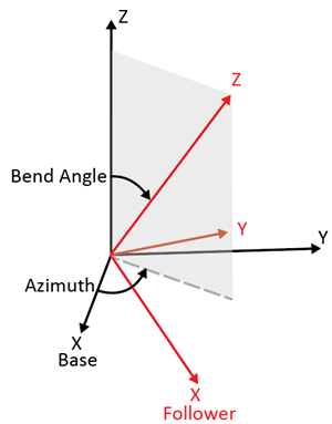
The black and red frames indicate the base and follower frames of the block. The azimuth rotation about the Z-axis of the base frame locates the plane in which the bend angle occurs. The bend angle about the resulting Y-axis, the red Y-axis, specifies the orientation of the Z-axis of the follower frame with respect to the Z-axis of the base frame.
The block has two parameterizations, Rotation Sequence (faster
simulation)
or Quaternion (allows zero bend
angle)
, to specify the internal states of the joint. Use the
rotation-sequence parameterization whenever possible because a simulation with this
parameterization is generally faster than a simulation with the quaternion
parameterization. See Internal State for more information.
You can specify the desired initial states of the joint with the parameters under State Targets, such as the position and velocity of the azimuth and bend angle.
The block has a variety of sensing abilities. You can sense the azimuth, bend angle, and their time derivatives throughout the simulation. Furthermore, you can sense the forces and torques that act in the joint, such as constraint forces and total torque. For more information, see Composite Force/Torque Sensing section.
Examples
Modeling Constant Velocity Joints - Power Take-Off Shaft
A Power Take-Off (PTO) shaft, a device for transferring power from tractor engines to auxiliary equipment such as soil tillers and wood chippers. The model includes two PTO subsystems identical in every sense but their joints. One contains universal (U) joints, the other constant-velocity (CV) joints.
Ports
Frame
B — Base frame
frame
Port associated with the base frame of the joint block. In typical applications where a CV joint couples two shafts, the Z-axis of base frame is aligned with the driving shaft.
F — Follower frame
frame
Port associated with the follower frame of the joint block. In typical applications where a CV joint couples two shafts, the Z-axis of follower frame is aligned with the driven shaft.
Input
mode — Joint mode control
physical signal
Input port that controls the mode of the joint. The signal must be a unitless scalar. The
joint mode is normal when the input signal is 0
, disengaged when
the input signal is -1
, and locked when the input signal is
1
. You can change the mode at any time during the
simulation.
The table shows how the position and velocity of the joint change during transitions between modes.
Transitions | Position | Velocity |
---|---|---|
Normal to Locked | The joint position retains the current value and remains constant after the transition. | The joint velocity becomes zero and remains constant after the transition. |
Normal to Disengaged | The joint position retains the current value but can change in any direction after the transition. | The joint velocity retains the current value but can change in any direction after the transition. |
Locked to Normal | The joint position retains the current value but can change in the directions aligned with the joint degrees of freedom (DOFs) after the transition. | The joint velocity remains at zero but can change in the directions aligned with the joint DOFs after the transition. |
Locked to Disengaged | The joint position retains the current value but can change in any direction after the transition. | The joint velocity remains at zero but can change in any direction after the transition. |
Disengaged to Normal | For the directions aligned with the joint DOFs, the joint positions initially take values calculated by using Newton's method and can change thereafter. In the constrained directions, the joint positions become zero and remain constant after the transition. | For the directions aligned with the joint DOFs, the joint velocities initially take values calculated by using Newton's method and can change thereafter. In the constrained directions, the joint velocities become zero and remain constant after the transition. |
Disengaged to Locked | For the directions aligned with the joint DOFs, the joint positions initially take values calculated by using Newton's method and remain constant after the transition. In the constrained directions, the joint positions become zero and remain constant after the transition. | The joint velocity becomes zero and remains constant after the transition. |
Dependencies
To enable this port, under Mode Configuration, set Mode to Provided by Input
.
Output
qb — Bend angle
scalar
Bend angle of the CV joint, returned as a scalar. This quantity is the angle between the Z-axes of the base and follower frames of the block.
Dependencies
To enable this port, under Constant Velocity Primitive (CV) > Sensing > Bend Angle, select Position.
wb — Velocity of bend angle
scalar
Velocity of the bend angle of the CV joint, returned as a scalar. This quantity equals the time derivative of the signal output from port qb.
Dependencies
To enable this port, under Constant Velocity Primitive (CV) > Sensing > Bend Angle, select Velocity.
bb — Acceleration of bend angle
scalar
Acceleration of the bend angle of the CV joint, returned as a scalar. This quantity equals the second time derivative of the signal output from port qb.
Dependencies
To enable this port, under Constant Velocity Primitive (CV) > Sensing > Bend Angle, select Acceleration.
qa — Azimuth
scalar
Azimuth of the CV joint, returned as a scalar. This quantity is the angle of the rotation about the Z-axis of the base frame. The rotation locates the plane in which the bend angle occurs.
Dependencies
To enable this port, under Constant Velocity Primitive (CV) > Sensing > Azimuth, select Position.
wa — Velocity of azimuth
scalar
Velocity of the azimuth of the CV joint, returned as a scalar. This quantity equals the time derivative of the signal output from port qa.
Dependencies
To enable this port, under Constant Velocity Primitive (CV) > Sensing > Azimuth, select Velocity.
ba — Acceleration of azimuth
scalar
Acceleration of the azimuth of the CV joint, returned as a scalar. This quantity equals the second time derivative of the signal output from port qa.
Dependencies
To enable this port, under Constant Velocity Primitive (CV) > Sensing > Azimuth, select Acceleration.
fc — Constraint force
scalar
Constraint force that acts in the joint, returned as a scalar. The force maintains the translational constraints of the joint. See Measure Joint Constraint Forces for more information.
Dependencies
To enable this port, under Composite Force/Torque Sensing, select Constraint Force.
tc — Constraint torque
scalar
Constraint torque acting in the joint, returned as a scalar. The torque maintains the rotational constraints of the joint. See Force and Torque Sensing for more information.
Dependencies
To enable this port, under Composite Force/Torque Sensing, select Constraint Torque.
ft — Total force
scalar
Total force acting in the joint, returned as a scalar. The total force is the sum of forces transmitted from one frame to the other through the joint. The force includes actuation, internal, and constraint forces. See Force and Torque Sensing for more information.
Dependencies
To enable this port, under Composite Force/Torque Sensing, select Total Force.
tt — Total torque
scalar
Total torque acting in the joint, returned as a scalar. The total torque is the sum of torques transmitted from one frame to the other through the joint. The torque includes actuation, internal, and constraint torques. See Force and Torque Sensing for more information.
Dependencies
To enable this port, under Composite Force/Torque Sensing, select Total Torque.
Parameters
Constant Velocity Primitive (CV)
Internal State — Internal state parameterization of joint
Rotation Sequence (faster
simulations)
(default) | Quaternion (allows zero bend
angle)
Choose the parameterization to specify the internal states of the joint.
Rotation Sequence (faster simulations)
The Constant Velocity Joint block uses the Z-Y-Z rotation sequence parameterization. The angle of the second Z-axis rotation is the negative of the angle of the first Z-axis rotation.
Use this method whenever possible because a simulation with this parameterization is generally faster than a simulation with the quaternion parameterization. However, the Z-Y-Z rotation sequence parameterization has a kinematic singularity when the bend angle is zero. If zero bend angle is required, set Internal State to
Quaternion (allows zero bend angle)
.
Quaternion (allows zero bend angle)
The Constant Velocity Joint block uses the quaternion parameterization. To enforce the CV kinematic constraint, the fourth component of the quaternion, the Z-component of the vector part, is always zero.
Use this method when zero bend angle is required. This method does not have a kinematic singularity at zero bend angle but has a kinematic singularity when the bend angle is 180 degrees. A simulation with this parameterization is generally slower than a simulation with the Z-Y-Z parameterization.
State Targets > Specify Position Target — Whether to specify position target
off
(default) | on
Select this parameter to enable parameters for specifying the position target of the joint.
State Targets > Specify Position Target > Priority — Priority level of position target
High (desired)
(default) | Low (approximate)
Set the priority level of the position target. See Guiding Assembly for more information.
Dependencies
To enable this parameter, under Constant Velocity Primitive (CV) > State Targets, select Specify Position Target.
State Targets > Specify Position Target > Value — Angles to specify position target
Bend Angle Only
(default) | Bend Angle and Azimuth
Whether to specify the position target of the CV joint at the start of simulation using only the bend angle or the bend angle and the azimuth.
Dependencies
To enable this parameter, under Constant Velocity Primitive (CV) > State Targets, select Specify Position Target.
State Targets > Specify Position Target > Value > Bend Angle — Bend angle to specify
45 deg
(default)
Specify the bend angle of the CV joint.
Dependencies
To enable this parameter, under Constant Velocity Primitive (CV) > State Targets, select Specify Position Target.
State Targets > Specify Position Target > Value > Azimuth — Azimuth to specify
0 deg
(default)
Specify the azimuth of the CV joint.
Dependencies
To enable this parameter, under Constant Velocity Primitive (CV) > State Targets > Specify Position Target > Value, select Bend Angle and Azimuth.
State Targets > Specify Velocity Target — Whether to specify velocity target
off
(default) | on
Select this parameter to enable parameters for specifying the velocity target of the joint.
State Targets > Specify Velocity Target > Priority — Priority level of velocity target
High (desired)
(default) | Low (approximate)
Set the priority level of the velocity target. See Guiding Assembly for more information.
Dependencies
To enable this parameter, under Constant Velocity Primitive (CV) > State Targets, select Specify Velocity Target.
State Targets > Specify Velocity Target > Value — Parameters to specify velocity target
Bend Angle Only
(default) | Bend Angle and Azimuth
Whether to specify the velocity target of the CV joint at the start of simulation using only the bend angle or the bend angle and the azimuth.
Dependencies
To enable this parameter, under Constant Velocity Primitive (CV) > State Targets, select Specify Velocity Target.
State Targets > Specify Velocity Target > Value > Bend Angle — Bend angle velocity to specify
0 deg/s
(default)
Specify the bend angle velocity of the CV joint.
Dependencies
To enable this parameter, under Constant Velocity Primitive (CV) > State Targets, select Specify Velocity Target.
State Targets > Specify Velocity Target > Value > Azimuth — Azimuth velocity to specify
0 deg/s
(default)
Specify the azimuth velocity of the CV joint.
Dependencies
To enable this parameter, under Constant Velocity Primitive (CV) > State Targets > Specify Velocity Target > Value, select Bend Angle and Azimuth.
Sensing > Bend Angle > Position — Whether to sense bend angle
off (default) | on
Select this parameter to enable the port qb.
Sensing > Bend Angle > Velocity — Whether to sense velocity of bend angle
off (default) | on
Select this parameter to enable the port wb.
Sensing > Bend Angle > Acceleration — Whether to sense acceleration of bend angle
off (default) | on
Select this parameter to enable the port bb.
Sensing > Azimuth > Position — Whether to sense azimuth
off (default) | on
Select this parameter to enable the port qa.
Sensing > Azimuth > Velocity — Whether to sense velocity of azimuth
off (default) | on
Select this parameter to enable the port wa.
Sensing > Azimuth > Acceleration — Whether to sense acceleration of azimuth
off (default) | on
Select this parameter to enable the port ba.
Mode Configuration
Mode — Joint mode
Normal
(default) | Locked
| Disengaged
| Provided by Input
Joint mode for the simulation, specified as one of these values:
Mode | Description |
---|---|
Locked | Locked mode constrains all the degrees of freedom (DOFs) for the joint. The locked joint maintains its initial assembly position with zero velocity during the simulation. The joint block can sense forces or torques in accordance with the settings of the Internal Mechanics, Limits, and Actuation parameters. |
Normal | Normal mode enables the DOFs and the constraints of the joint work as intended during the simulation. |
Disengaged | Disengaged mode releases the joint from all constraints throughout the simulation. The settings for Internal Mechanics, Limits, and Actuation parameters do not affect the disengaged joint. All output ports output zero. |
Provided by Input | The Provided by Input option allows you to specify the joint mode
by using an input signal. For more information, see the port
mode in the Input
section. |
Composite Force/Torque Sensing
Direction — Measurement direction
Follower on Base
(default) | Base on Follower
Measurement direction, specified as one of these values:
Follower on Base
— The block senses the force and torque that the follower frame exerts on the base frame.Base on Follower
— The block senses the force and torque that the base frame exerts on the follower frame.
This parameter affects only the output signals under the Composite Force/Torque Sensing section. Reversing the direction changes the sign of the measurements. For more information, see Force and Torque Measurement Direction.
Resolution Frame — Frame used to resolve measurements
Base
(default) | Follower
Frame used to resolve the measurements, specified as one of these values:
Base
— The block resolves the measurements in the coordinates of the base frame.Follower
— The block resolves the measurements in the coordinates of the follower frame.
This parameter affects only the output signals under the Composite Force/Torque Sensing section.
Extended Capabilities
C/C++ Code Generation
Generate C and C++ code using Simulink® Coder™.
Version History
Introduced in R2015a
MATLAB Command
You clicked a link that corresponds to this MATLAB command:
Run the command by entering it in the MATLAB Command Window. Web browsers do not support MATLAB commands.
Select a Web Site
Choose a web site to get translated content where available and see local events and offers. Based on your location, we recommend that you select: .
You can also select a web site from the following list
How to Get Best Site Performance
Select the China site (in Chinese or English) for best site performance. Other MathWorks country sites are not optimized for visits from your location.
Americas
- América Latina (Español)
- Canada (English)
- United States (English)
Europe
- Belgium (English)
- Denmark (English)
- Deutschland (Deutsch)
- España (Español)
- Finland (English)
- France (Français)
- Ireland (English)
- Italia (Italiano)
- Luxembourg (English)
- Netherlands (English)
- Norway (English)
- Österreich (Deutsch)
- Portugal (English)
- Sweden (English)
- Switzerland
- United Kingdom (English)
Asia Pacific
- Australia (English)
- India (English)
- New Zealand (English)
- 中国
- 日本Japanese (日本語)
- 한국Korean (한국어)