How Multibody Assembly Works
You model an articulated system by interconnecting bodies through joints and occasionally gears and other constraints. Bodies contribute their inertias to the model, while joints, gears, and constraints determine the relative degrees of freedom that exist between the bodies. You interconnect the two component types by linking frame ports on joint, gear, and constraint blocks to frame ports on body subsystems.
Simscape™ Multibody™ automatically assembles your model when you update the block diagram. During model update, Simscape Multibody determines the initial states of joints—their positions and velocities—so that the resulting assembly satisfies all kinematic constraints in the model. This process occurs in two phases, with the assembly algorithm first computing the joint positions and then the joint velocities. The complete process is called model assembly.
Connecting Joints
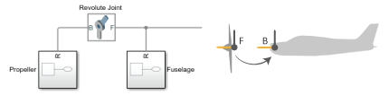
Joints connect to bodies through frames. Each joint block contains two frame ports, base (B) and follower (F), identifying the connection points in the adjoining bodies and the relative directions they can move in. When you connect these ports to frames in the body subsystems, you determine how the bodies themselves connect upon model assembly.
Joint Frames Identifying Connection Points and Rotation Axis of Aircraft Propeller
If a joint has no actuation and no sensing outputs, its frame ports are fully interchangeable. In this case, you can switch the bodies that the ports connect to without affecting model dynamics or joint sensing outputs. If the joint does have actuation inputs or sensing outputs, you may need to reverse the actuation or sensing signals to obtain the same dynamic behavior and simulation results.
To change the connection points of a joint, you must modify the connection frames in the adjoining body subsystems. You do this by specifying a translation transform using a Rigid Transform block. You can add new Rigid Transform blocks to the body subsystems or, if appropriate, change the translation transforms in existing Rigid Transform subsystems.
For more information on how Simscape Multibody software interprets frame ports, nodes, and lines, see Working with Frames.
Orienting Joints
To obtain the motion expected in a model, you must align its various joint motion axes properly. This means aligning the joints themselves as observed or anticipated in the real system. Misaligning the joint axes may lead to unexpected motion but it often leads to something more serious, such as a failure to assemble and simulate.
You can specify and change joint alignment by rotating the connection frames local to the adjoining body subsystems. For this purpose, you specify rotation transforms using Rigid Transform blocks, either by adding new blocks to the body subsystems or, if appropriate, by changing the rotation transforms in existing blocks within the subsystems.
Why change the orientation of joints through body subsystem frames? Each primitive in a joint block has a predetermined motion axis, such as x or z. The axis definition is fixed and cannot be changed. Realigning the connection frames local to the adjoining body subsystems provides a natural way to reorient joints while avoiding confusion over which axis a particular joint uses.
Guiding Assembly
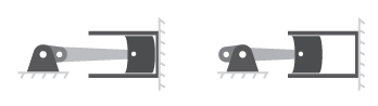
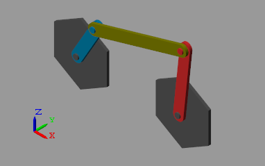
Joints can start simulation from different states. For example, the crank joint of a crank-rocker linkage can start at any angle from 0° to 360°. As a result, during model assembly, Simscape Multibody must choose from many equally valid states. You can guide the states chosen by specifying state targets in the joint block dialog boxes.
Crank-Slider Mechanism in Fully Extended and Fully Retracted Initial Configurations
State targets need not be exact values. If Simscape Multibody cannot achieve a state target exactly, it searches for the joint state nearest to the state target. For example, if you specify a position state target of 60° but the joint can only reach angles of 0° to 45°, Simscape Multibody attempts to assemble the joint at 45°.
How close the actual joint state is to the state target depends on the kinematic constraints in your model, any conflicts with other state targets, and the state target priority level—a ranking that determines which of two state targets to satisfy if they prove to be mutually incompatible. You can set the priority level to Low or High.
Simscape Multibody first attempts to satisfy all state targets exactly. If a state target conflict arises, Simscape Multibody ignores the low-priority state targets and attempts to satisfy only the high-priority state targets. If a state target conflict still exists, Simscape Multibody ignores also the high-priority state targets and attempts to assemble the model in the nearest valid configuration.
You can specify state targets for all joints in an open kinematic chain. However, to avoid simulation errors, every closed chain must contain at least one joint without state targets.
Verifying Model Assembly
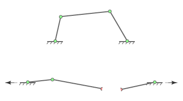
A model assembles successfully only if the connections between its bodies are congruous with each other. If in satisfying one kinematic constraint, Simscape Multibody must violate another kinematic constraint, the model is kinematically invalid and assembly fails. This happens, for example, when the ground link of a four-bar assembly exceeds the combined length of the remaining three links, preventing at least one joint from assembling.
Joint Assembly Failure in Four-Bar Linkage with Exceedingly Long Ground Link
To ensure that your model has assembled correctly, use these Simscape Multibody and Simscape utilities:
Multibody Explorer — Simscape Multibody visualization utility. Visually examine your model from different points of view to ensure that its bodies connect at the expected locations and with the proper orientations.
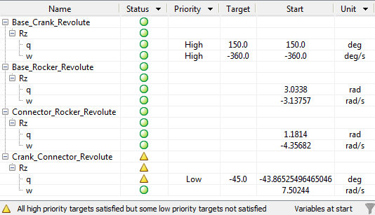
Variable Viewer — Simscape state-reporting utility. Check the assembly status of individual joints and constraints and compare your state targets to the actual joint states achieved during assembly.
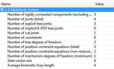
Statistics Viewer — Simscape metrics-reporting utility. Check, among other metrics, the degrees of freedom, number of joints, and number of constraints in your model.