Gain Goal
Purpose
Limit gain of a specified input/output transfer function, when using Control System Tuner.
Description
Gain Goal limits the gain from specified inputs to specified outputs. If you specify
multiple inputs and outputs, Gain Goal limits the largest singular value of the transfer
matrix. (See sigma for more information about singular
values.) You can specify a constant maximum gain at all frequencies. Alternatively, you can
specify a frequency-dependent gain profile.
Use Gain Goal, for example, to enforce a custom roll-off rate in a particular frequency band. To do so, specify a maximum gain profile in that band. You can also use Gain Goal to enforce disturbance rejection across a particular input/output pair by constraining the gain to be less than 1.
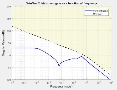
When you create a tuning goal in Control System Tuner, a tuning-goal plot is generated. The dotted line shows the gain profile you specify. The shaded area on the plot represents the region in the frequency domain where the gain goal is not satisfied.
By default, Gain Goal constrains a closed-loop gain. To constrain a gain computed with one or more loops open, specify loop-opening locations in the I/O Transfer Selection section of the dialog box.
Creation
In the Tuning tab of Control System Tuner, select New Goal > Gain limits to create a Gain Goal.
Command-Line Equivalent
When tuning control systems at the command line, use TuningGoal.Gain to specify a maximum gain goal.
I/O Transfer Selection
Use this section of the dialog box to specify the inputs and outputs of the transfer function that the tuning goal constrains. Also specify any locations at which to open loops for evaluating the tuning goal.
Specify input signals
Select one or more signal locations in your model as inputs to the transfer function that the tuning goal constrains. To constrain a SISO response, select a single-valued input signal. For example, to constrain the gain from a location named
'u'to a location named'y', click Add signal to list and select
 'u'. To constrain the largest singular value of a MIMO response, select multiple signals or a vector-valued signal.Specify output signals
Select one or more signal locations in your model as outputs of the transfer function that the tuning goal constrains. To constrain a SISO response, select a single-valued output signal. For example, to constrain the gain from a location named
'u'to a location named'y', click
Add signal to list and select 'y'. To constrain the largest singular value of a MIMO response, select multiple signals or a vector-valued signal.Compute input/output gain with the following loops open
Select one or more signal locations in your model at which to open a feedback loop for the purpose of evaluating this tuning goal. The tuning goal is evaluated against the open-loop configuration created by opening feedback loops at the locations you identify. For example, to evaluate the tuning goal with an opening at a location named
'x', click
Add signal to list and select 'x'.
Tip
To highlight any selected signal in the Simulink® model, click ![]() . To remove a signal from the input or output list, click
. To remove a signal from the input or output list, click ![]() . When you have selected multiple signals, you can reorder
them using
. When you have selected multiple signals, you can reorder
them using ![]() and
and ![]() . For more information on how to specify signal locations
for a tuning goal, see
Specify Goals for Interactive Tuning.
. For more information on how to specify signal locations
for a tuning goal, see
Specify Goals for Interactive Tuning.
Options
Use this section of the dialog box to specify additional characteristics of the gain goal.
Limit gain to
Enter the maximum gain in the text box. You can specify a scalar value or a frequency-dependent gain profile. To specify a frequency-dependent gain profile, enter a SISO numeric LTI model. For example, you can specify a smooth transfer function (
tf,zpk, orssmodel). Alternatively, you can sketch a piecewise maximum gain using anfrdmodel. When you do so, the software automatically maps the profile to a smooth transfer function that approximates the desired minimum disturbance rejection. For example, to specify a gain profile that rolls off at –40dB/decade in the frequency band from 8 to 800 rad/s, enterfrd([0.8 8 800],[10 1 1e-4]).You must specify a SISO transfer function. If you specify multiple input signals or output signals, the gain profile applies to all I/O pairs between these signals.
If you are tuning in discrete time, you can specify the maximum gain profile as a discrete-time model with the same sampling time as you use for tuning. If you specify the gain profile in continuous time, the tuning software discretizes it. Specifying the gain profile in discrete time gives you more control over the gain profile near the Nyquist frequency.
Stabilize I/O transfer
By default, the tuning goal imposes a stability requirement on the closed-loop transfer function from the specified inputs to outputs, in addition to the gain constraint. If stability is not required or cannot be achieved, select
Noto remove the stability requirement. For example, if the gain constraint applies to an unstable open-loop transfer function, selectNo.Enforce goal in frequency range
Limit the enforcement of the tuning goal to a particular frequency band. Specify the frequency band as a row vector of the form
[min,max], expressed in frequency units of your model. For example, to create a tuning goal that applies only between 1 and 100 rad/s, enter[1,100]. By default, the tuning goal applies at all frequencies for continuous time, and up to the Nyquist frequency for discrete time.Adjust for signal amplitude
When this option is set to
No, the closed-loop transfer function being constrained is not scaled for relative signal amplitudes. When the choice of units results in a mix of small and large signals, using an unscaled transfer function can lead to poor tuning results. Set the option toYesto provide the relative amplitudes of the input signals and output signals of your transfer function.For example, suppose the tuning goal constrains a 2-input, 2-output transfer function. Suppose further that second input signal to the transfer function tends to be about 100 times greater than the first signal. In that case, select
Yesand enter[1,100]in the Amplitude of input signals text box.Adjusting signal amplitude causes the tuning goal to be evaluated on the scaled transfer function Do–1T(s)Di, where T(s) is the unscaled transfer function. Do and Di are diagonal matrices with the Amplitude of output signals and Amplitude of input signals values on the diagonal, respectively.
Apply goal to
Use this option when tuning multiple models at once, such as an array of models obtained by linearizing a Simulink model at different operating points or block-parameter values. By default, active tuning goals are enforced for all models. To enforce a tuning requirement for a subset of models in an array, select Only Models. Then, enter the array indices of the models for which the goal is enforced. For example, suppose you want to apply the tuning goal to the second, third, and fourth models in a model array. To restrict enforcement of the requirement, enter
2:4in the Only Models text box.For more information about tuning for multiple models, see Robust Tuning Approaches (Robust Control Toolbox).
Algorithms
Evaluating Tuning Goals
When you tune a control system, the software converts each tuning goal into a normalized scalar value f(x). Here, x is the vector of free (tunable) parameters in the control system. The software then adjusts the parameter values to minimize f(x) or to drive f(x) below 1 if the tuning goal is a hard constraint.
For Gain Goal, f(x) is given by:
or its discrete-time equivalent. Here,
T(s,x) is the closed-loop
transfer function between the specified inputs and outputs, evaluated with parameter
values x. Do and
Di are the scaling matrices described in
Options. denotes the H∞ norm
(see getPeakGain).
The frequency weighting function WF is the
regularized gain profile, derived from the maximum gain profile you specify. The gain of
WF roughly matches the inverse of the gain
profile you specify, inside the frequency band you set in the Enforce goal in
frequency range field of the tuning goal.
WF is always stable and proper. Because poles
of WF(s) close to
s = 0 or s = Inf might lead to
poor numeric conditioning for tuning, it is not recommended to specify maximum gain
profiles with very low-frequency or very high-frequency dynamics. For more information
about regularization and its effects, see Visualize Tuning Goals.
Implicit Constraints
This tuning goal also imposes an implicit stability constraint on the closed-loop transfer function between the specified inputs to outputs, evaluated with loops opened at the specified loop-opening locations. The dynamics affected by this implicit constraint are the stabilized dynamics for this tuning goal. The Minimum decay rate and Maximum natural frequency tuning options control the lower and upper bounds on these implicitly constrained dynamics. If the optimization fails to meet the default bounds, or if the default bounds conflict with other requirements, on the Tuning tab, use Tuning Options to change the defaults.