kaiserord
Kaiser window FIR filter design estimation parameters
Syntax
Description
[
returns a filter order n,Wn,beta,ftype] = kaiserord(f,a,dev)n, normalized frequency band edges
Wn, and a shape factor beta that specify a Kaiser
window for use with the fir1 function. To design an FIR filter
b that approximately meets the specifications given by
f, a, and dev, use b =
fir1(n,Wn,kaiser(n+1,beta),ftype,"noscale").
Examples
Design a lowpass filter with passband defined from 0 to 1 kHz and stopband defined from 1500 Hz to 4 kHz. Specify a passband ripple of 5% and a stopband attenuation of 40 dB.
fsamp = 8000;
fcuts = [1000 1500];
mags = [1 0];
devs = [0.05 0.01];

[n,Wn,beta,ftype] = kaiserord(fcuts,mags,devs,fsamp);
hh = fir1(n,Wn,ftype,kaiser(n+1,beta),"noscale");

freqz(hh,1,1024,fsamp)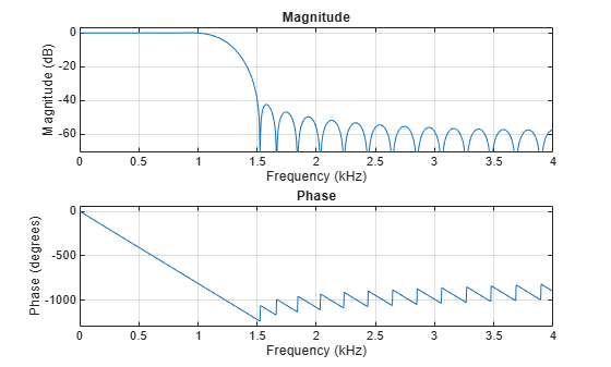
Design an odd-length bandpass filter. Note that odd length means even order, so the input to fir1 must be an even integer.
fsamp = 8000;
fcuts = [1000 1300 2210 2410];
mags = [0 1 0];
devs = [0.01 0.05 0.01];

[n,Wn,beta,ftype] = kaiserord(fcuts,mags,devs,fsamp);
n = n + rem(n,2);
hh = fir1(n,Wn,ftype,kaiser(n+1,beta),"noscale");

[H,f] = freqz(hh,1,1024,fsamp);
plot(f,abs(H))
grid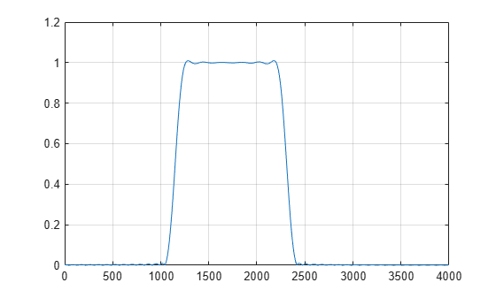
Design a lowpass filter with a passband cutoff of 1500 Hz, a stopband cutoff of 2000 Hz, a passband ripple of 0.01, a stopband ripple of 0.1, and a sample rate of 8000 Hz.
fs = 8000;
[n,Wn,beta,ftype] = kaiserord([1500 2000],[1 0],...
    [0.01 0.1],fs);
b = fir1(n,Wn,ftype,kaiser(n+1,beta),"noscale");
freqz(b,1,[],fs)
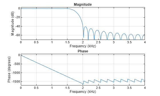
Design an equivalent filter using the "cell" option.
c = kaiserord([1500 2000],[1 0],[0.01 0.1],fs,"cell");
bcell = fir1(c{:});
freqz(bcell,1,[],fs)
Input Arguments
Output Arguments
Tips
Be careful to distinguish between the meanings of filter length and filter order. The filter length is the number of impulse response samples in the FIR filter. Generally, the impulse response is indexed from n = 0 to n = L – 1, where L is the filter length. The filter order is the highest power in a Z-transform representation of the filter. For an FIR transfer function, this representation is a polynomial in z, where the highest power is zL–1 and the lowest power is z0. The filter order is one less than the length (L – 1) and is also equal to the number of zeros of the z polynomial.
If, in the vector
dev, you specify unequal deviations across bands, the minimum specified deviation is used, since the Kaiser window method is constrained to produce filters with minimum deviation in all of the bands.In some cases,
kaiserordunderestimates or overestimates the ordern. If the filter does not meet the specifications, try a higher order such asn+1,n+2, and so on, or a try lower order.Results are inaccurate if the cutoff frequencies are near 0 or the Nyquist frequency, or if
devis large (greater than 10%).
Algorithms
Given a set of specifications in the frequency domain, kaiserord
estimates the minimum FIR filter order that will approximately meet the specifications.
kaiserord converts the given filter specifications into passband and
stopband ripples and converts cutoff frequencies into the form needed for windowed FIR filter
design.
kaiserord uses empirically derived formulas for estimating the orders
of lowpass filters, as well as differentiators and Hilbert transformers. Estimates for
multiband filters (such as bandpass filters) are derived from the lowpass design
formulas.
The design formulas that underlie the Kaiser window and its application to FIR filter design are
where α = –20log10δ is the stopband attenuation expressed in decibels, and
where n is the filter order and Δω is the width of the smallest transition region.
References
[1] Digital Signal Processing Committee of the IEEE Acoustics, Speech, and Signal Processing Society, eds. Selected Papers in Digital Signal Processing. Vol. II. New York: IEEE Press, 1976.
[2] Kaiser, James F. “Nonrecursive Digital Filter Design Using the I0-Sinh Window Function.” Proceedings of the 1974 IEEE International Symposium on Circuits and Systems. 1974, pp. 20–23.
[3] Oppenheim, Alan V., Ronald W. Schafer, and John R. Buck. Discrete-Time Signal Processing. Upper Saddle River, NJ: Prentice Hall, 1999.
Extended Capabilities
Version History
Introduced before R2006a