firpmord
Parks-McClellan optimal FIR filter order estimation
Description
Examples
Design a minimum-order lowpass filter with a 500 Hz passband cutoff frequency and 600 Hz stopband cutoff frequency. Specify a sample rate of 2000 Hz. Require at least 40 dB of attenuation in the stopband and less than 3 dB of ripple in the passband.
rp = 3;           % Passband ripple in dB
rs = 40;          % Stopband ripple in dB
fs = 2000;        % Sample rate
f = [500 600];    % Cutoff frequencies
a = [1 0];        % Desired amplitudes
Convert the deviations to linear units. Design the filter and visualize its magnitude and phase responses.
dev = [(10^(rp/20)-1)/(10^(rp/20)+1) 10^(-rs/20)];
[n,fo,ao,w] = firpmord(f,a,dev,fs);
b = firpm(n,fo,ao,w);
freqz(b,1,1024,fs)
title("Lowpass Filter Designed to Specifications")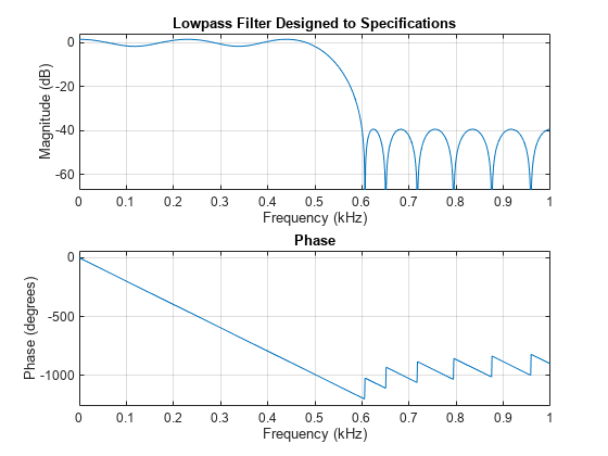
The filter falls slightly short of meeting the stopband attenuation and passband ripple specifications. Using n+1 instead of n in the call to firpm achieves the desired amplitude characteristics.
Design a lowpass filter with a 1500 Hz passband cutoff frequency and a 2000 Hz stopband cutoff frequency. Specify a sample rate of 8000 Hz. Require a maximum stopband amplitude of 0.1 and a maximum passband error (ripple) of 0.01.
[n,fo,ao,w] = firpmord([1500 2000],[1 0],[0.01 0.1],8000);
b = firpm(n,fo,ao,w);
Obtain an equivalent result by having firpmord generate a cell array. Visualize the frequency response of the filter.
c = firpmord([1500 2000],[1 0],[0.01 0.1],8000,"cell");
B = firpm(c{:});
freqz(B,1,1024,8000)
Input Arguments
Output Arguments
Algorithms
The firpmord function uses the algorithm presented in [1]. This function produces
inaccurate results for band edges close to either 0 or the Nyquist frequency,
fs/2.
Note
In some cases,
firpmordunderestimates or overestimates the ordern. If the filter does not meet the specifications, try a higher order such asn+1orn+2.In some cases, the algorithm estimates a negative value for the filter order. If that happens, the function returns
nas0.
References
[1] Rabiner, Lawrence R., and Otto Herrmann. “The Predictability of Certain Optimum Finite-Impulse-Response Digital Filters.” IEEE® Transactions on Circuit Theory. Vol. 20, Number 4, 1973, pp. 401–408.
[2] Rabiner, Lawrence R., and Bernard Gold. Theory and Application of Digital Signal Processing. Englewood Cliffs, NJ: Prentice-Hall, 1975, pp. 156–157.
Extended Capabilities
Version History
Introduced before R2006a