Main Content

besself

Bessel analog filter design

Description

[b,a] = besself(n,Wo) returns the transfer function coefficients of an nth-order lowpass analog Bessel filter, where Wo is the angular frequency up to which the filter's group delay is approximately constant. Larger values of n produce a group delay that better approximates a constant up to Wo. The besself function does not support the design of digital Bessel filters.

example

[z,p,k] = besself(___) designs a lowpass analog Bessel filter and returns its zeros, poles, and gain.

example

[A,B,C,D] = besself(___) designs an analog Bessel filter and returns the matrices that specify its state-space representation.

Examples

collapse all

Design a fifth-order analog lowpass Bessel filter with approximately constant group delay up to 104 rad/second. Plot the magnitude and phase responses of the filter using freqs.

wc = 10000;
[b,a] = besself(5,wc);
freqs(b,a)

Figure contains 2 axes objects. Axes object 1 with xlabel Frequency (rad/s), ylabel Phase (degrees) contains an object of type line. Axes object 2 with xlabel Frequency (rad/s), ylabel Magnitude contains an object of type line.

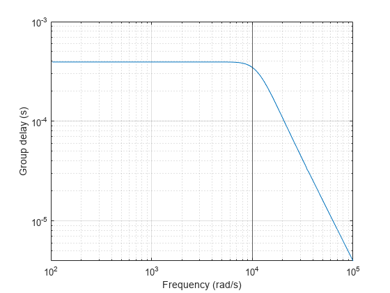
Compute the group delay response of the filter as the negative of the derivative of the unwrapped phase response. Plot the group delay to verify that it is approximately constant up to the cutoff frequency.

[h,w] = freqs(b,a);
grpdel = -diff(unwrap(angle(h)))./diff(w);

clf
loglog(w(2:end),grpdel)
xlabel("Frequency (rad/s)")
ylabel("Group delay (s)")
xline(wc)
grid on

Figure contains an axes object. The axes object with xlabel Frequency (rad/s), ylabel Group delay (s) contains 2 objects of type line, constantline.

Design a fourth-order digital IIR filter with maximally flat group delay from its analog filter equivalent.

Design an analog lowpass fourth-order Bessel filter with cutoff frequency of 300 Hz.

[b,a] = besself(4,2*pi*300);

Use the impulse invariance method to convert from analog to digital filter. The sample rate is 1000 Hz.

Fs = 10000;
[bd,ad] = impinvar(b,a,Fs);

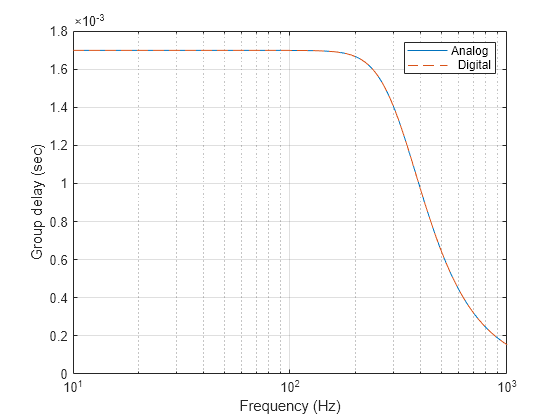
Compute the frequency response and group delay of the analog and digital Bessel filters. Specify 2048 frequency points geometrically distributed between 1 Hz and 1 kHz. Plot the group delay responses. Both designs yield the same result.

f = logspace(1,3,2048);

HfAnalog = freqs(b,a,2*pi*f);
HfDigital = freqz(bd,ad,2*pi*f/Fs);
gdAnalog = -diff(unwrap(angle(HfAnalog)))./diff(2*pi*f);
gdDigital = -diff(unwrap(angle(HfDigital)))./diff(2*pi*f);

semilogx(f(2:end),gdAnalog,"-",f(2:end),gdDigital,"--")
xlabel("Frequency (Hz)")
ylabel("Group delay (sec)")
legend(["Analog","  Digital"])
grid on

Figure contains an axes object. The axes object with xlabel Frequency (Hz), ylabel Group delay (sec) contains 2 objects of type line. These objects represent Analog, Digital.

Design a fifth-order analog Butterworth lowpass filter with a cutoff frequency of 2 GHz. Multiply by 2π to convert the frequency to radians per second. Compute the frequency response of the filter at 4096 points.

n = 5;
wc = 2*pi*2e9;
w = 2*pi*1e9*logspace(-2,1,4096)';

[zb,pb,kb] = butter(n,wc,"s");
[bb,ab] = zp2tf(zb,pb,kb);
[hb,wb] = freqs(bb,ab,w);
gdb = -diff(unwrap(angle(hb)))./diff(wb);

Design a fifth-order Chebyshev Type I filter with the same edge frequency and 3 dB of passband ripple. Compute its frequency response.

[z1,p1,k1] = cheby1(n,3,wc,"s");
[b1,a1] = zp2tf(z1,p1,k1);
[h1,w1] = freqs(b1,a1,w);
gd1 = -diff(unwrap(angle(h1)))./diff(w1);

Design a fifth-order Chebyshev Type II filter with the same edge frequency and 30 dB of stopband attenuation. Compute its frequency response.

[z2,p2,k2] = cheby2(n,30,wc,"s");
[b2,a2] = zp2tf(z2,p2,k2);
[h2,w2] = freqs(b2,a2,w);
gd2 = -diff(unwrap(angle(h2)))./diff(w2);

Design a fifth-order elliptic filter with the same edge frequency, 3 dB of passband ripple, and 30 dB of stopband attenuation. Compute its frequency response.

[ze,pe,ke] = ellip(n,3,30,wc,"s");
[be,ae] = zp2tf(ze,pe,ke);
[he,we] = freqs(be,ae,w);
gde = -diff(unwrap(angle(he)))./diff(we);

Design a fifth-order Bessel filter with the same edge frequency. Compute its frequency response.

[zf,pf,kf] = besself(n,wc);
[bf,af] = zp2tf(zf,pf,kf);
[hf,wf] = freqs(bf,af,w);
gdf = -diff(unwrap(angle(hf)))./diff(wf);

Plot the attenuation in decibels. Express the frequency in gigahertz. Compare the filters.

fGHz = [wb w1 w2 we wf]/(2e9*pi);
plot(fGHz,mag2db(abs([hb h1 h2 he hf])))
axis([0 5 -45 5])
grid on
xlabel("Frequency (GHz)")
ylabel("Attenuation (dB)")
legend(["butter" "cheby1" "cheby2" "ellip" "besself"])

Figure contains an axes object. The axes object with xlabel Frequency (GHz), ylabel Attenuation (dB) contains 5 objects of type line. These objects represent butter, cheby1, cheby2, ellip, besself.

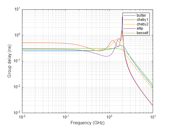
Plot the group delay in samples. Express the frequency in gigahertz and the group delay in nanoseconds. Compare the filters.

gdns = [gdb gd1 gd2 gde gdf]*1e9;
gdns(gdns<0) = NaN;
loglog(fGHz(2:end,:),gdns)
grid on
xlabel("Frequency (GHz)")
ylabel("Group delay (ns)")
legend(["butter" "cheby1" "cheby2" "ellip" "besself"])

Figure contains an axes object. The axes object with xlabel Frequency (GHz), ylabel Group delay (ns) contains 5 objects of type line. These objects represent butter, cheby1, cheby2, ellip, besself.

The Butterworth and Chebyshev Type II filters have flat passbands and wide transition bands. The Chebyshev Type I and elliptic filters roll off faster but have passband ripple. The frequency input to the Chebyshev Type II design function sets the beginning of the stopband rather than the end of the passband. The Bessel filter has approximately constant group delay along the passband.

Input Arguments

collapse all

Filter order, specified as an integer scalar less than or equal to 25. For bandpass and bandstop designs, n represents one-half the filter order.

Data Types: double

Cutoff frequency, specified as a positive scalar. A cutoff frequency is an upper or lower bound of the frequency range in which the filter's group delay is approximately constant. Express the cutoff frequency in radians per second.

Data Types: double

Output Arguments

collapse all

Transfer function coefficients of the filter, returned as row vectors of length n + 1 for lowpass and highpass filters and 2n + 1 for bandpass and bandstop filters. The transfer function is expressed in terms of b and a as

H(s)=b1sr1+b2sr2++bra1sr1+a2sr2++ar

Data Types: double

Zeros, poles, and gain of the filter, returned as two column vectors of length n (2n for bandpass and bandstop designs) and a scalar. The transfer function is expressed in terms of z, p, and k as

H(s)=k(sz1)(sz2)(szr)(sp1)(sp2)(spr)

Data Types: double

State-space representation of the filter, returned as matrices. If m = n for lowpass and highpass designs and m = 2n for bandpass and bandstop filters, then A is m × m, B is m × 1, C is 1 × m, and D is 1 × 1.

The state-space matrices relate the state vector x, the input u, and the output y through

x˙=Ax+Buy=Cx+Du.

Data Types: double

Algorithms

besself designs analog Bessel filters, which are characterized by an almost constant group delay across the entire passband, thus preserving the wave shape of filtered signals in the passband.

Lowpass Bessel filters have a monotonically decreasing magnitude response, as do lowpass Butterworth filters. Compared to the Butterworth, Chebyshev, and elliptic filters, the Bessel filter has the slowest rolloff and requires the highest order to meet an attenuation specification.

For high-order filters, the state-space form is the most numerically accurate, followed by the zero-pole-gain form. The transfer function coefficient form is the least accurate; numerical problems can arise for filter orders as low as 15.

besself uses a four-step algorithm:

  1. Find lowpass analog prototype poles, zeros, and gain using the besselap function.

  2. Convert the poles, zeros, and gain into state-space form.

  3. Use the lp2lp function to convert the continuous-time state-space lowpass filter prototype to a lowpass filter with the specified cutoff frequency.

  4. Convert the state-space filter back to transfer function or zero-pole-gain form, as required.

References

[1] Parks, Thomas W., and C. Sidney Burrus. Digital Filter Design. New York: John Wiley & Sons, 1987.

Version History

Introduced before R2006a