Linearize Simulink Models Using MPC Designer
This topic shows how to linearize Simulink® models using MPC Designer. To do so, open the app from a Simulink model that contains an MPC Controller block. For this example,
use the CSTR_ClosedLoop model.
open_system('CSTR_ClosedLoop')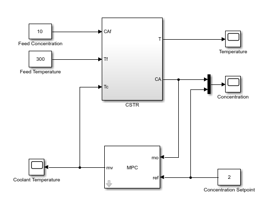
In the model window, double-click the MPC Controller block.
Tip
In the MPC Controller Block Parameters dialog box, in the Default Conditions tab, you can define the controller sample time and signal dimensions before opening MPC Designer.
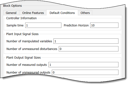
In the Block Parameters dialog box, ensure that the MPC Controller field is empty, and click Design to open MPC Designer.
Using MPC Designer, you can define the MPC structure by linearizing the Simulink model. After you define the initial MPC structure, you can also linearize the model at different operating points and import the linearized plants.
Note
If a controller from the MATLAB® workspace is specified in the MPC Controller field, the app imports the specified controller. In that case, the MPC structure is derived from the imported controller. However, you can still linearize the Simulink model and import the linearized plants.
Define MPC Structure by Linearization
This example shows how to define the plant input/output structure in MPC Designer by linearizing a Simulink model.
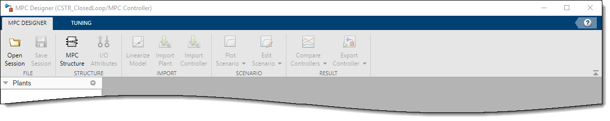
On the MPC Designer tab, in the Structure section, click MPC Structure.
Specify Signal Dimensions
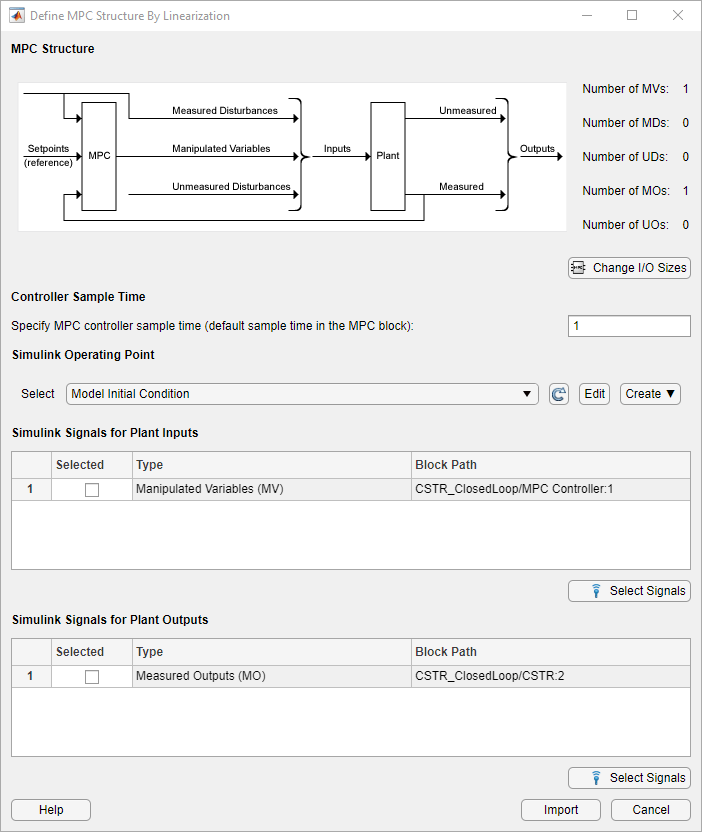
In the Define MPC Structure By Linearization dialog box, in the MPC Structure section, if the displayed signal dimensions do not match your model, click Change I/O Sizes to configure the dimensions. Since unmeasured disturbances or unmeasured outputs in your model do not input to the MPC Controller block, you must specify the dimensions for these signals. For this example, specify one unmeasured disturbance signal.
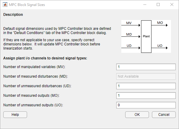
Click OK.
The Unmeasured Disturbance (UD) type is added in the Simulink Signals for Plant Inputs, without a specified block path.
Select Plant Input/Output Signals
Before linearizing the model, assign Simulink signal lines to each MPC signal type in your model. The app uses these signals as linearization inputs and outputs.
In the Simulink Signals for Plant Inputs and Simulink Signals for Plant Outputs sections, the Block Path is automatically defined for manipulated variables, measured outputs, and measured disturbances. MPC Designer detects these signals since they are connected to the MPC Controller block. If your plant has unmeasured disturbances or unmeasured outputs, select their corresponding Simulink signal lines.
To choose a signal type, use the Selected check boxes.
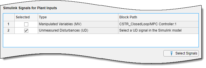
Click Select Signals. The Select Signals for MPC Input Channels dialog box opens up.
In the Simulink model window, click the signal line corresponding to the selected signal type.
The signal is highlighted, and its block path is added to the Select signals dialog box.
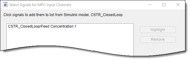
In the select signals dialog box, click OK.
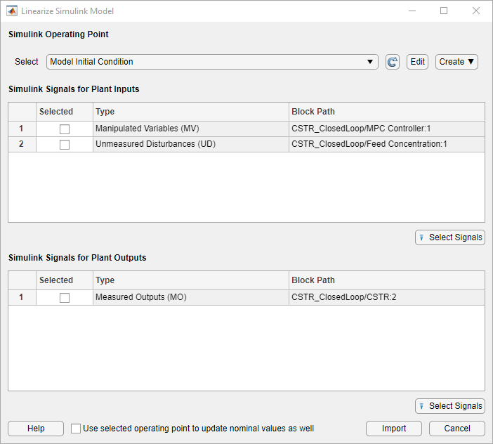
In the Define MPC Structure By Linearization dialog box, the Block Path for the selected signal type updates.
Note
If your model has measured disturbances, you must connect the
md input port of the MPC Controller block to the
same signal line of the corresponding plant inputs. For more information, see Connect Measured Disturbances for Linearization.
Specify Operating Point
In the Simulink Operating Point section, in the drop-down list, select an operating point at which to linearize the model. For this example, select Model Initial Condition.
For information on the different operating point options, see Specifying Operating Points.
Note
If you select an option that generates multiple operating points for linearization, MPC Designer uses only the first operating point to define the plant structure and linearize the model.
Define Structure and Linearize Model
Click Import.
MPC Designer linearizes the Simulink model at the specified operating point using the specified input/output signals, and imports the linearized plant to the Plants workspace, on the right hand side of the app. A default controller, which uses the linearized plant as its internal model and input/output signal values at the selected operating point as nominal values, is added to the Controllers workspace. A default simulation scenario is also added to the Scenarios workspace.
Note
All the controller created in the MPC Designer share the same nominal values, since otherwise it would not be easy to compare their responses. Therefore, if you update the nominal values, all the controllers are affected.
Linearize Model
After you define the initial MPC structure, you can linearize the Simulink model at different operating points and import the linearized plants. Doing so is useful for validating controller performance against modeling errors.
On the MPC Designer tab, in the Import section, click Linearize Model.
Select Plant Input/Output Signals
In the Simulink Signals for Plant Inputs and Simulink Signals for Plant Outputs sections, the input/output signal configuration is the same as the one you specify when initially defining the MPC structure.
You cannot change the signal types and dimensions once the structure is defined. However, for each signal type, you can select different signal lines from your Simulink model. The selected lines must have the same dimensions as those defined in the current MPC structure.
Specify Operating Point
In the Simulink Operating Point section, in the drop-down list, you can select the operating points at which to linearize the model.
For information on the different operating point options, see Specifying Operating Points.
Linearize Model and Import Plant
If you click on Import, MPC Designer linearizes the Simulink model at the defined operating point and adds the linearized plant, a default controller and a default simulation scenario to the app workspaces on the right hand side, as previously described for the Import button of the Define MPC Structure By Linearization dialog box.
If you select the Use selected operating point to update nominal values as well option, the nominal values of all the controllers in the Controllers workspace of the app are updated using this operating point signal values.
If you select an option that generates multiple operating points for linearization (see Specifying Operating Points), the app linearizes the model at all the specified operating points. The linearized plants are added in the Plants workspace in the same order in which their corresponding operating points are defined. If you choose to update the nominal values, the app uses the signal values from the first operating point.
Specifying Operating Points
In the Simulink Operating Point section of either the Define MPC Structure By Linearization dialog box or the Linearize Simulink Model dialog box, in the drop-down list, you can select or create operating points for model linearization. For more information on finding steady-state operating points, see About Operating Points (Simulink Control Design) and Compute Steady-State Operating Points from Specifications (Simulink Control Design).
Select Model Initial Condition
To linearize the model using the initial conditions specified in the Simulink model as the operating point, select Model Initial Condition.
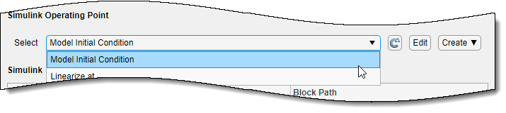
The model initial condition is the default operating point for linearization in MPC Designer.
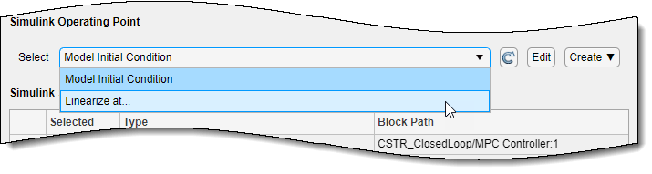
Linearize at Simulation Snapshot Times
To linearize the model at specified simulation snapshot times, select Linearize at. Linearizing at snapshot times is useful when you know that your model reaches an equilibrium state after a certain simulation time.
In the Enter snapshot times to linearize dialog box, in the Simulation snapshot times field, enter one or more simulation snapshot times. Enter multiple snapshot times as a vector.
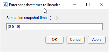
Click OK.
If you enter multiple snapshot times, and you previously selected Linearize at (and clicked on the Import button) from the:
Define MPC Structure By Linearization dialog box, MPC Designer linearizes the Simulink model using only the first snapshot time. The nominal values of the MPC controller are defined using the input/output signal values for this snapshot.
Linearize Simulink Model dialog box, MPC Designer linearizes the model at all the specified snapshot times. The linearized plant models are added to the Data Browser in the order specified in the snapshot time array. If you selected the Use selected operating point to update nominal values as well option, the nominal values are set using the input/output signal values from the first snapshot.
Compute Steady-State Operating Point
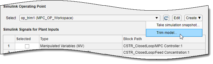
To compute a steady-state operating point using numerical optimization methods to meet your specifications, select Trim Model from the Create list.
In the Trim the model dialog box, enter the specifications for the steady-state values at which you want to find an operating point. You can specify values for states, input signals, and output signals.
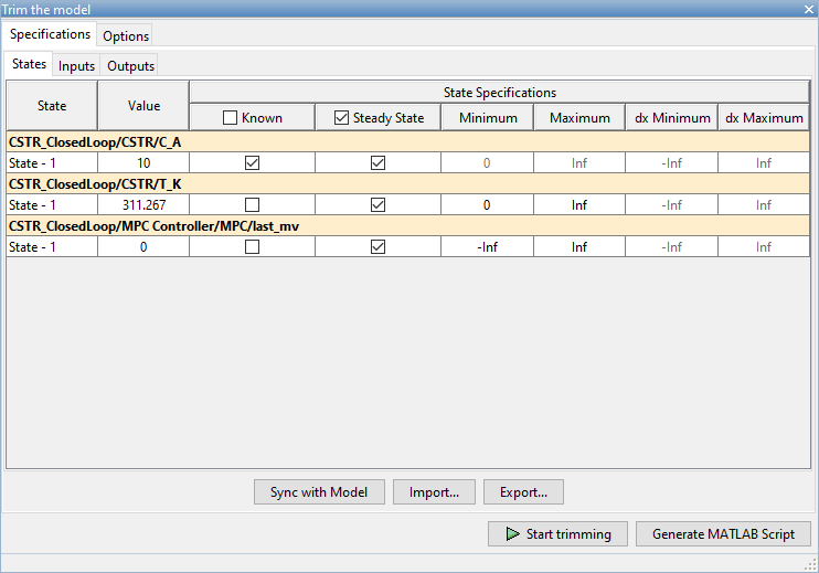
Click Start Trimming.
The Trim progress viewer window opens up showing the optimization progress towards finding a point in the state-input space of the model with the characteristics specified in the States, Inputs, and Outputs tabs. After the optimization process terminates, close the trim progress window as well as the Trim the model dialog box.
MPC Designer creates an operating point for the given specifications. The computed operating point is added to the Simulink Operating Point drop-down list and is selected.
For examples showing how to specify the conditions for a steady-state operating point search, see Compute Steady-State Operating Points from Specifications (Simulink Control Design).
Compute Operating Point at Simulation Snapshot Time
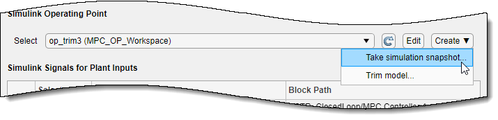
To compute operating points using simulation snapshots, select Take Simulation Snapshot. Linearizing the model using operating points computed from simulation snapshots is especially useful when you know that your model reaches an equilibrium state after a certain simulation time.
In the Enter snapshot times to linearize dialog box, in the Simulation snapshot times field, enter one or more simulation snapshot times. Enter multiple snapshot times as a vector.
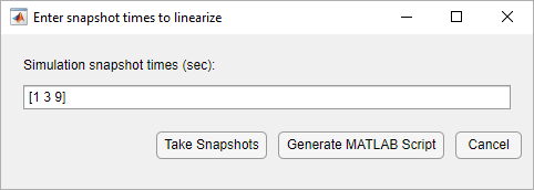
Click Take Snapshots.
MPC Designer simulates the Simulink model. At each snapshot time, the current state of the model is used to create an operating point, which is added to the drop-down list and selected.
If you enter multiple snapshot times, the operating points are stored together as an array. If you previously selected Take Simulation Snapshot from the:
Define MPC Structure By Linearization dialog box, MPC Designer linearizes the model using only the first operating point in the array. The nominal values of the MPC controller are defined using the input/output signal values for this operating point.
Linearize Simulink Model dialog box, MPC Designer linearizes the model at all the operating points in the array. The linearized plant models are added to the Data Browser in the same order as the operating point array.
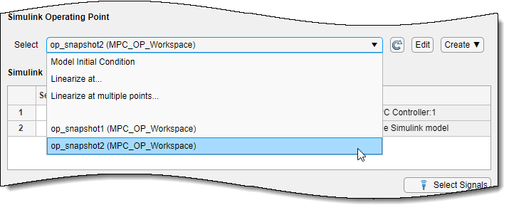
Select Existing Operating Point
Under Existing Operating Points, select a previously defined operating point at which to linearize the Simulink model. This option is available if one or more previously created operating points are available in the drop-down list.
If the selected operating point represents an operating point array created using multiple snapshot times, and you previously selected an operating point from the:
Define MPC Structure By Linearization dialog box, MPC Designer linearizes the model using only the first operating point in the array. The nominal values of the MPC controller are defined using the input/output signal values for this operating point.
Linearize Simulink Model dialog box, MPC Designer linearizes the model at all the operating points in the array. The linearized plant models are added to the Data Browser in the same order as the operating point array.
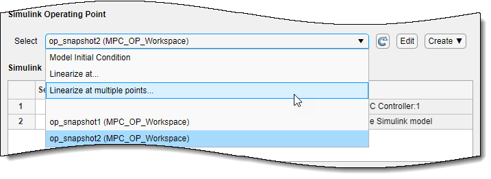
Select Multiple Operating Points
To linearize the Simulink model at multiple existing operating points, select Linearize at Multiple Points. This option is available if more than one previously created operating points are in the drop-down list.
In the Specify multiple operating points dialog box, select the operating points at which to linearize the model.
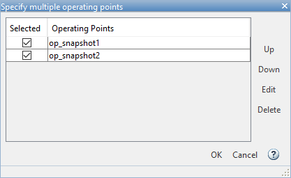
To change the operating point order, click an operating point in the list and click Up or Down to move the highlighted operating point within the list.
Click OK.
If you previously selected Linearize at Multiple Points and then clicked Import from the:
Define MPC Structure By Linearization dialog box, MPC Designer linearizes the model using only the first specified operating point. The nominal values of the MPC controller are defined using the input/output signal values for this operating point.
Linearize Simulink Model dialog box, MPC Designer linearizes the model at all the specified operating points. The linearized plant models are added to the Data Browser in the order specified in the Specify multiple operating points dialog box.
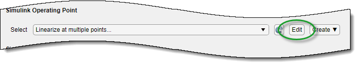
View/Edit Operating Point
To view or edit the selected operating point, click the Edit button.
In the Edit dialog box, if you created the selected operating point from a simulation snapshot, you can edit the operating point values.
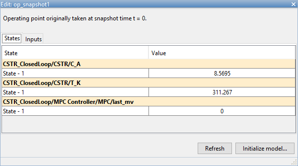
If the selected operating point represents an operating point array, in the Select Operating Point drop-down list, select an operating point to view.
If you obtained the operating point by trimming the model, you can only view the operating point values.
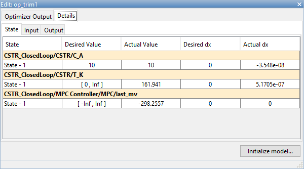
To set the Simulink model initial conditions to the states in the operating point, click Initialize model. You can then simulate the model at the specified operating point.
When setting the model initial conditions, MPC Designer exports the operating point to the MATLAB workspace. Also, in the Simulink Configuration Parameters dialog box, in the Data Import/Export section, it selects the Input and Initial state parameters and configures them to use the states and inputs in the exported operating point.
To reset the model initial conditions, for example, if you delete the exported operating point, clear the Input and Initial state parameters.
Connect Measured Disturbances for Linearization
If your Simulink model has measured disturbance signals, connect them to the corresponding
plant input ports and to the md port of the MPC Controller
block. If you have multiple measured disturbances, connect them to the MPC
Controller using a vector signal. As discussed in Define MPC Structure by Linearization, MPC Designer automatically
detects the measured disturbances connected to the MPC Controller block and
sets them as plant inputs for linearization.
Because the measured disturbances connected to the md port are selected
as linearization inputs, you must connect the plant measured disturbance input ports to the
selected signal line, as shown in the following diagram.
Correct MD Connection
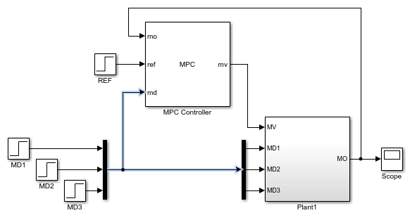
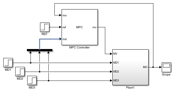
If you connect the plant measured disturbance input ports to the corresponding signals
before the Mux block, as shown in the following diagram, there is no
linearization path from the signals at the md port to the plant. As a
result, when you linearize the plant using MPC Designer, the measured disturbance
channels linearize to zero.
Incorrect MD Connection
See Also
Apps
Functions
linearize(Simulink Control Design)