IP Core Clock Interface
The clock interface for an IP core determines the IP core execution rate, drives the IP core internal logic, and synchronize the data movement between the IP core algorithm and peripheral interfaces. The IP core can have two types of clock inputs, the IP core clock and the register interface clock. The IP core clock drives the internal logic of the algorithm and peripheral interfaces. The register interface clock drives the AXI4 or AXI4-Lite register interface and synchronizes the data movement between registers and the IP core algorithm. The IP core clock interface is closely related to the IP core reset interface. The reset signals transitions the IP core to a known, stable state when the hardware powers up. To learn about the reset interface, see IP Core Reset Interface.
IP Core Clock
The rates in your model determine the clock domains of your IP core. You can choose to generate either a single clock input or multiple clock inputs for the clock domains:
To generate a single-clock set the Clock inputs model configuration parameter to
Single. HDL Coder™ generates a single clock and reset input for all rates in your model. The clock input drives the fastest rate, and the internal timing controller logic produces slower rates.To generate multiple-clocks, set the Clock inputs model configuration parameter to
Multiple. HDL Coder generates an independent pair of clock and reset inputs for each rate in your model.
Register Interface Clock
When you use a register interface in your IP core, HDL Coder generates a separate clock and reset input for the register interface. When you choose the AXI4-Lite protocol, the port names are AXI4_Lite_ACLK and AXI4_Lite_ARESETN. When you choose the AXI4 protocol, the port names are AXI4_ACLK and AXI4_ARESETN. To learn more about register interfaces, see Model Design for AXI4 Register Interface Generation.
For AXI4-Lite register interfaces, the AXI4_Lite_ACLK input can share the same clock as IPCORE_CLK or use an independent clock. When using an independent AXI4_Lite_ACLK, you must enable the Enable clock domain crossing on AXI4-Lite registers setting. Clock domain crossing is not supported for full AXI4 register interfaces. The AXI4_ACLK must use the same clock source as the IPCORE_CLK. For more information, see Different Clock Inputs for IP Core Clock and Register Interface Clock.
Enable and Reset System Registers
When you use a register interface in your IP core, HDL Coder generates two registers related to the clock interface:
A reset register that has the address
0x0. Write a1to this register to reset the entire IP core. Because the register value automatically clears, you do not have to write a0to this register.An enable register that has the address
0x4. Write a0to this register to disable the IP core or a1to enable the entire IP core. The default value of this register is1.
This image shows an IP core with a single-clock. The IP core has input ports for an IP core clock and reset, and a register interface clock and reset.
This table summarizes the different clock styles and their use cases.
| IP Core Clock | Register Interface Clock | Description | Use Cases |
|---|---|---|---|
| Single Clock Input | Same as IP core clock | The register interface clock and reset must be connected to the same source as the IP core clock and reset. | The IP core requires a software configuration, and both the control and data paths use the same system clock. |
| Different from IP core clock | The register interface clock and reset connections can be different from the IP core clock and reset ports. | The IP core requires a software configuration, and the IP core algorithm runs at a different clock frequency than the register interface clock frequency. | |
| None | The IP core does not have a register interface. HDL Coder only generates the IP core clock and IP core reset ports. | The IP core is pure data path logic with fixed behavior and no run-time configuration. | |
| Multiple Clock Inputs | Same as one IP core clock | You must connect the register interface clock and reset to the same source as the IP core clock and reset interfaces that correspond to the ports mapped to the register interface. | The software control belongs to a specific clock domain. The IP core must internally manage or process data across additional clock domains |
| Different from all IP core clocks | The register interface clock and reset connections can be different from the IP core clock and resets. | The IP core is a self-contained multiple-clock system. The software must interact with the IP core asynchronously. | |
| None | The IP core does not have a register interface. HDL Coder only generates the IP core clock and IP core reset ports. | The IP core consists of multiple clock data movements and the software control is either not necessary or is handled externally. |
Single Clock Input
When all rates are synchronous and can be driven by the same clock, use a single clock input. IP cores that use a single clock input lead to a smaller hardware footprint and simplified timing closure during the synthesis and implementation phases. When you have a single clock, HDL Coder generates only one set of clock, clock enable, and reset ports for all the rates in the Simulink® model.
Same Clock Input for IP Core Clock and Register Interface Clock
When the register interface and IP core DUT algorithm use the same clock, connect the IP core clock, IPCORE_CLK and register clock, AXI4_LITE_ACLK clocks to the same clock source, and connect the IP core reset, IPCORE_RESETN and register reset, AXI4_LITE_ARESETN ports to the same reset source, as shown in this image. To learn how the reset logic works, see IP Core Reset Interface.
The register interface consists of logic for:
Communication with external IP by using the AXI4-Lite or AXI4 protocol
Address decoding and registers accessible through an AXI4 or AXI4-Lite interface
The register interface clock drives this logic.
Different Clock Inputs for IP Core Clock and Register Interface Clock
To use independent clocks for the IP core and register interfaces, enable clock domain crossing (CDC) for the IP core.
Clock domain crossing is supported only when you set the Synthesis
Tool parameter in the Target pane of the
model configuration parameters to Xilinx Vivado and
the Interface parameter in the target interface table in
the Target Interface pane to
AXI4-Lite. Use clock domain crossing when:
The register interface clock runs on a clock with a lower frequency than the DUT IP core.
The register interface runs on a clock with a higher frequency than the DUT IP core.
The register interface and the DUT IP core use asynchronous clocks.
When you enable CDC, HDL Coder inserts synchronization and back-pressure logic to safely transfer signals between the AXI4-Lite clock domain and the IP core clock domain.
For more information, see Enable Clock Domain Crossing on AXI4-Lite Interfaces.
IP Core without Register Interface
When you have an application that does not require an AXI4 register interface,
set the Generate default register interface parameter to
off. For example, when you have an IP core algorithm that
takes a switch input and turns on an LED and you want the algorithm to run at
the clock rate, generate an IP core without a register interface.
This image shows the generated clock for an IP core with no register interface. By default, the clock enable connects to a logical true, which means that the DUT or algorithm logic is always enabled.
If you want to expose the clock enable signal to the top-level IP core clock interface, use these options:
| Parameter Name | Description | Notes |
|---|---|---|
| Expose DUT clock enable input port | Select this option if you want to expose the DUT clock enable input port. Trigger the DUT from upstream IPs by using the clock enable input port. | You can use this option only when
GenerateDefaultRegisterInterface
is set to off. |
| Expose DUT clock enable output port | Select this option if you want to expose the clock enable output port to downstream IPs. Drive or synchronize downstream custom IPs by using the clock enable output port. |
Multiple Clock Inputs
Since R2026a
You can generate an IP core that has multiple clocks from a multirate Simulink
design, by setting the Clock inputs model
configuration parameter to Multiple. When you select this
setting, HDL Coder generates a separate clock input for each rate in your DUT.
When you generate an IP core with multiple clocks, these limitations apply:
The Synthesis Tool parameter in the Target pane of the model configuration parameters must be set to
Xilinx Vivado.The Target Platform parameter in the Target pane of the model configuration parameters must be set to
Generic Xilinx Platform.You can map the DUT ports to only AXI4-Lite or External Port interfaces. When you map DUT ports to AXI4-Lite interfaces, the AXI4-Lite mapped DUT ports must all run at the same rate.
Only multiple rate, multiple-clock modeling is supported. Trigger-as-clock modeling is not supported.
You cannot expose DUT clock enable ports.
You cannot generate an IP core that uses multiple clocks by using the HDL Workflow Advisor. You must use the IP Core Editor or the MATLAB® command line.
Use Same Clock for IP Core and Register Interface
When you disable the Clock Domain Crossing on AXI4-Lite
Registers parameter in the Interface
Settings tab of the IP Core Editor, the AXI4-Lite clock must
share the same clock input as one of the IP core clocks. The IP core generation
report indicates which IP core clock to use for the AXI4-Lite clock. If you do
not map any DUT ports to AXI4-Lite interfaces and set the Generate
default register interface parameter in the Interface Settings tab of the IP Core Editor to
on, you must connect the AXI4-Lite clock to the IP core
clock that corresponds to the fastest rate in the design.
This image shows an IP core with multiple-clocks and no CDC. The AXI4_LITE_ACLK and IPCORE_CLK clock ports are connected to the fastest clock in the design.
Use Independent Clock for Register Interface
To use an independent clock for the AXI4-Lite register interface, select the Enable clock domain crossing on AXI4-Lite registers parameter in the Interface Settings pane of the IP Core Editor. When you select this option, HDL Coder adds logic for crossing the clock domains between the AXI4_LITE_ACLK and the IPCORE_CLK clocks.
This image shows an IP core with multiple-clocks and CDC enabled. You can connect different clock signals to the IP core clocks and register interface clocks.
When you enable clock domain crossing for AXI4-Lite registers, HDL Coder supports these scenarios:
The DUT has mapped registers and the register interface runs on a different clock than the clock driving the mapped ports.
The DUT has no user mapped registers, and the register interface runs on a different clock than the fastest IPCORE_CLK.
The IP core register interface and the DUT use asynchronous clocks.
Multiple Clock IP Core without Register Interface
When you have an application that does not require an AXI4 register interface,
set the Generate default register interface parameter in
the Interface Settings tab of the IP Core
Editor to off. For example, when you have an always-on or
data driven hardware application such as ASIC or SoC verification, streaming
data paths, or designs where you handle the clock control externally, generate a
multiple-clock IP core without a register interface.
This image shows the generated clocks for an IP core with no register interface. The clock enable connects to a logical true, which means that the DUT or algorithm logic is always enabled.
Clock Enable Signals and Constraints
When you generate an IP core that has multiple clocks without a register
interface, the multiple clock enable DUT ports share the same
dut_enable signal. HDL Coder connects the dut_enable signal to a constant
1, always enabling the IP core. When a register interface
is present, write a value of 1 to the enable register to
enable the register interface clock domain. HDL Coder independently synchronizes the dut_enable
signal with each IP core clock domain and drives the corresponding clock enable
ports.
Each clock domain uses a two-stage register synchronizer to synchronize the enable value from the AXI4-Lite register clock domain to the destination clock domain. The enable register is in the clock domain associated with the AXI4-Lite registers.
HDL Coder uses the ASYNC_REG attribute to indicate that
the outputs of the two registers form a synchronizer that transfers signals
between the clock domains. HDL Coder does not add these constraints during single-clock IP core
generation.
IP Core Generation Report
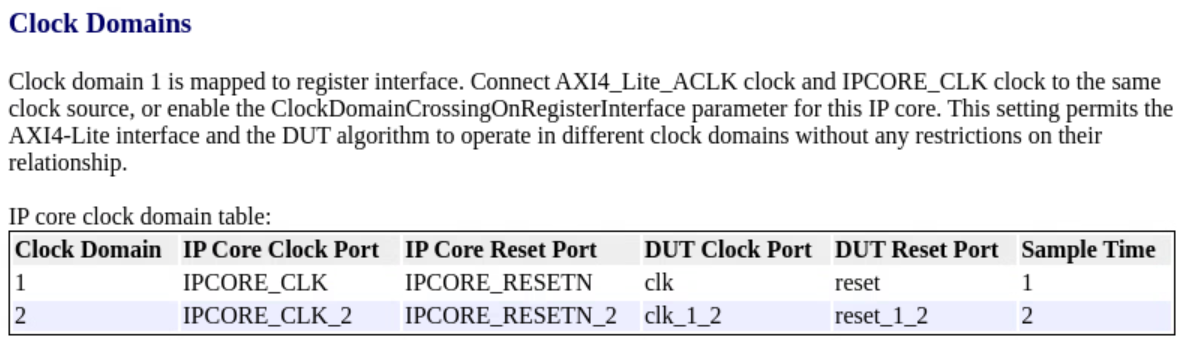
When you generate an IP core report for a model that has multiple clock IP
cores, the code generation report includes a Clock Domain
column that indicates the clock domain that the DUT port belongs to.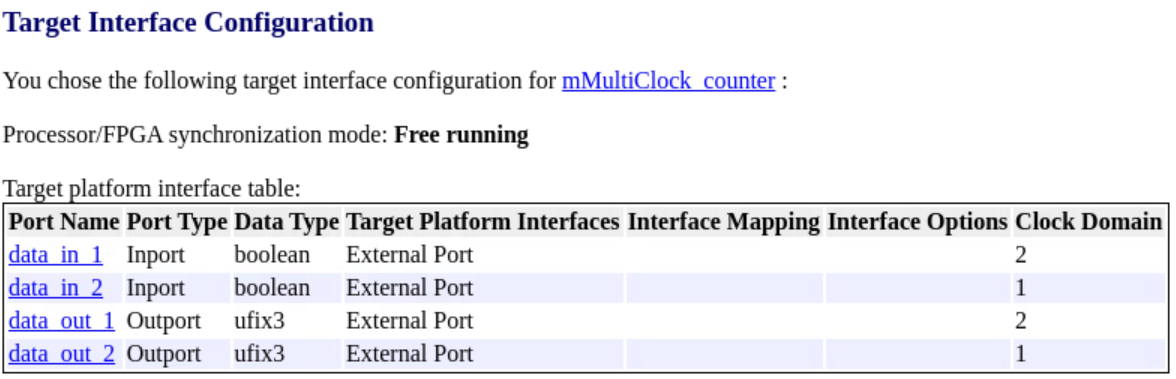
If you do not enable clock domain crossing for an AXI4 interface, the code generation report includes a section that describes the AXI4 clock and IP core clock connections.