Sine Wave
R2026bGenerate continuous or discrete sine wave
Sine Wave block

To add a block to a model, double-click the canvas and start typing the block name. Then, select the block from the list.
Libraries:
DSP System Toolbox /
Sources
DSP System Toolbox HDL Support /
Sources
Description
The Sine Wave block generates a multichannel real or complex sinusoidal signal, with independent amplitude, frequency, and phase in each output channel. The block supports floating point and signed fixed-point data types.
When you set the Computation
method parameter to Table lookup and the
Optimize table for parameter to
Speed, you can specify the frequency of the sine wave as
any scalar or vector of scalars. The block generates a sine wave whose frequency is the
closest achievable approximation using a table of length equal to the Maximum
table length parameter. (since R2026b)
The block generates a real sinusoidal signal when you set the Output
complexity parameter to Real. The real
sinusoidal output is defined by an expression of the type
where you specify A in the Amplitude parameter, f in hertz in the Frequency parameter, and ϕ in radians in the Phase offset parameter.
The block generates a complex exponential signal when you set the Output
complexity parameter to Complex. This complex
exponential signal is defined by an expression of the type
Generating Multichannel Outputs
For both real and complex sinusoids, the Amplitude, Frequency, and Phase offset parameter values (A, f, and ϕ) can be scalars or length-N vectors, where N is the desired number of channels in the output. When you specify at least one of these parameters as a length-N vector, scalar values specified for the other parameters are applied to every channel.
For example, to generate the three-channel output containing the following real sinusoids, set the block parameters as shown:
Output complexity =
RealAmplitude =
[1 2 3]Frequency =
[1000 500 250]Phase offset =
[0 0 pi/2]
Examples
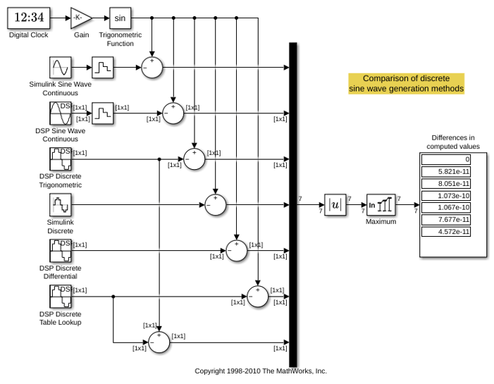
This example compares the different methods of generating sample-based sine waves from the Sine Wave block in DSP System Toolbox.
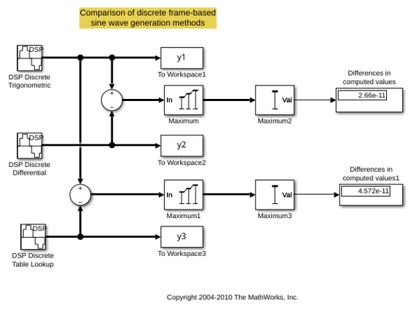
This example compares the different methods of generating frame-based sine waves from the Sine Wave block in DSP System Toolbox™.
Ports
Output
Output a sinusoidal signal as a scalar, vector, or a matrix. For more information about output complexity, see Description. For information about multichannel support, see Generating Multichannel Outputs.
Tip
To output fixed-point data types, you must set Sample
mode to Discrete and
Computation method to Table
lookup.
Data Types: single | double | fixed point
Complex Number Support: Yes
Parameters
Main Tab
A length-N vector containing the amplitudes of the sine waves in each of N output channels, or a scalar to be applied to all N channels. The vector length must be the same as that specified for the Frequency and Phase offset parameters.
Tip
This parameter is tunable (Simulink) only when the Computation
method is Trigonometric
fcn or
Differential.
Tunable: Yes
A length-N vector containing frequencies, in hertz, of the sine waves in each of N output channels, or a scalar to be applied to all N channels. The vector length must be the same as that specified for the Amplitude and Phase offset parameters. You can specify positive, zero, or negative frequencies.
Tip
This parameter is tunable (Simulink) when you set:
Solver Type to
Fixed-step.Sample mode to
Continuous.Sample mode to
Discreteand Computation method toTrigonometric fcn.
Tunable: Yes
A length-N vector containing the phase offsets, in radians, of the sine waves in each of N output channels, or a scalar to be applied to all N channels. The vector length must be the same as that specified for the Amplitude and Frequency parameters.
Tip
This parameter is tunable (Simulink) when you set:
Solver Type to
Fixed-step.Sample mode to
Continuous.Sample mode to
Discreteand Computation method toTrigonometric fcn.
Tunable: Yes
Specify the sampling mode as Continuous or
Discrete:
ContinuousIn continuous mode, the sinusoid in the ith channel, yi, is computed as a continuous function,
and the block's output is continuous. In this mode, the block operates the same as the Simulink® Sine Wave block with Sample time set to
0. This mode offers high accuracy, but requires trigonometric function evaluations at each simulation step, which is computationally expensive. Also, because this method tracks absolute simulation time, a discontinuity will eventually occur when the time value reaches its maximum limit.Note also that many DSP System Toolbox™ blocks do not accept continuous-time inputs.
DiscreteIn discrete mode, the block can generate discrete-time output by directly evaluating the trigonometric function, by table lookup, or by a differential method. For more information on these computation methods, see Algorithms.
The type of waveform to generate: Real
specifies a real sine wave, Complex specifies
a complex exponential.
The method by which discrete-time sinusoids are generated:
Trigonometric fcn, Table
lookup, or Differential.
For more information on each of the available options, see Algorithms.
Dependencies
This parameter is only visible when you set the Sample
mode to Discrete.
Note
To generate fixed-point sinusoids, you must set the
Computation method to
Table
									lookup
.
Optimize the table of sine values for one of the following:
Speed–– The block precomputes a full table of sine values. The block supports arbitrary frequencies and sample rates. If the specified frequency is not exactly representable in the table, the block uses the closest representable frequency given the Maximum table length constraint. Use the read-only fields in the Info section to verify the frequency of the generated signal.Memory–– The table contains k/4 elements, where k = Fs/F. The period of each sinusoid must be an integer multiple of 4/Fs.
Dependencies
To enable this parameter, set:
Sample mode to
DiscreteComputation method to
Table lookup
Specify the maximum number of elements in the sine table as a positive integer less than 107. The block uses a lookup table with at most this many elements to represent the sine wave. Increasing this value allows the block to represent more frequencies exactly, at the cost of additional memory.
For vector frequencies, this limit applies individually to each frequency.
Dependencies
To enable this parameter, set:
Sample mode to
DiscreteComputation method to
Table lookupOptimize table for to
Speed
The period with which the sine wave is sampled, Ts, as a finite scalar, greater than zero. The output frame period of the block is MTs, where you specify M in the Samples per frame parameter.
Dependencies
To enable this parameter, set Sample mode to
Discrete.
The number of consecutive samples from each sinusoid to buffer into the output frame, M, specified as a positive scalar integer. This parameter is not tunable.
The block output is an M-by-N matrix with frame period MTs, where you specify Ts in the Sample time parameter.
Dependencies
To enable this parameter, set Sample mode to
Discrete.
This parameter determines the behavior of the Sine Wave
block when an enabled subsystem is reenabled. The block can either reset
itself to its starting state (Restart at time
zero), or resume generating the sinusoid based on the
current simulation time (Catch up to simulation
time).
Dependencies
This parameter only applies when the Sine Wave
block is located inside an enabled subsystem and the
States when enabling parameter of the
Enable (Simulink) block is set
to reset.
Info
Since R2026b
This parameter is read-only.
Table length for the generated sine wave, displayed as a positive integer or a vector of length equal to the length of the Frequency (Hz) vector. Each element in the vector corresponds to the table length used for the respective frequency in the Frequency (Hz) parameter.
Dependencies
This field is visible when you set:
Sample mode to
DiscreteComputation method to
Table lookupOptimize table for to
Speed
Since R2026b
This parameter is read-only.
Actual frequency of the generated sine wave in Hz, displayed as a scalar or a vector of length equal to the length of the Frequency (Hz) vector. This is the closest representable frequency to the value you specify in the Frequency (Hz) parameter, given the Maximum table length constraint. The block wraps this value to the range [0, Fs).
Dependencies
This field is visible when you set:
Sample mode to
DiscreteComputation method to
Table lookupOptimize table for to
Speed
Since R2026b
This parameter is read-only.
Difference between the actual generated frequency and the specified
target frequency in Hz, displayed as a scalar or a vector of length
equal to the length of the Frequency (Hz) vector. A
value of 0 indicates that the specified target
frequency is exactly representable in the table.
Dependencies
This field is visible when you set:
Sample mode to
DiscreteComputation method to
Table lookupOptimize table for to
Speed
Data Types Tab
Select how you would like to specify the data type properties of the Output data type. You can choose:
Inherit:Inherit via back propagation— Inherit via the back propagation.Built in— Lets you specify a built-in data type, for example,double.Fixed point— Lets you specify the fixed-point attributes of the data type.Expression— Lets you specify an expression that evaluates to a valid data type, for example,fixdt(1,16).
Block Characteristics
Data Types |
|
Direct Feedthrough |
|
Multidimensional Signals |
|
Variable-Size Signals |
|
Zero-Crossing Detection |
|
More About
A real-valued, discrete-time sinusoid is defined as:
where A is the amplitude, f is the frequency in Hz, and φ is the initial phase, or phase offset, in radians.
A complex sinusoid is defined as:
Algorithms
When you select Discrete from the Sample
mode parameter, the secondary Computation method
parameter provides three options for generating the discrete sinusoid:
Trigonometric fcn, Table
lookup, and Differential.
The trigonometric function method computes the sinusoid in the ith channel, yi, by sampling the continuous function
with a period of Ts, where you specify
Ts in the Sample
time parameter. This mode of operation has the same benefits and
liabilities as the Continuous sample mode.
At each sample time, the block evaluates the sine function at the appropriate time value within the first cycle of the sinusoid. By constraining trigonometric evaluations to the first cycle of each sinusoid, the block avoids the imprecision of computing the sine of very large numbers, and eliminates the possibility of discontinuity during extended operations (when an absolute time variable might overflow). This method therefore avoids the memory demands of the table lookup method at the expense of many more floating-point operations.
The table lookup method precomputes unique samples of every output sinusoid at the start of simulation, and recalls the samples from memory as needed. A table of finite length can only be constructed when all output sequences repeat.
When you set the Optimize table for parameter to
Speed, the block precomputes a full table of sine
values and recalls the samples from memory as needed. The block supports arbitrary
frequencies and sample rates. If the frequency you specify is not exactly
representable in the table, the block uses the closest representable frequency given
the constraint of the Maximum table length parameter value. To
determine the actual frequency of the generated sine wave, use the read-only fields,
Actual frequency and Frequency error
in the Info section of the block dialog box.
When you set the Optimize table for parameter to
Memory, the block constructs a lookup table with
k/4 elements for each channel, where k =
Fs/F. Here, Fs =
1/Ts, Ts is the value of the
Sample time parameter, and F is the
frequency specified in the Frequency (Hz) parameter.
For long output sequences, the table lookup method requires far fewer floating-point operations than any of the other methods, but it can demand considerably more memory, especially for high sample rates (long tables). This method is recommended for models that are intended to emulate or generate code for DSP hardware and therefore must be optimized for execution speed.
Note
The lookup table for this block is constructed from double-precision
floating-point values. Thus, when you use the Table
lookup computation mode, the maximum amount of precision you
can achieve in your output is 53 bits. Setting the word length of the
Output or User-defined data type
to values greater than 53 bits does not improve the precision of your
output.
Tip
To generate fixed-point sinusoids, you must select Table
lookup.
The differential method uses an incremental algorithm. This algorithm computes the output samples based on the output values computed at the previous sample time (and precomputed update terms) by using the following identities.
The update equations for the sinusoid in the ith channel, yi, can therefore be written in matrix form as
where you specify Ts in the Sample time parameter. Since Ts is constant, the right-hand matrix is a constant and can be computed once at the start of the simulation. The value of Aisin[2πfi(t+Ts)+ϕi] is then computed from the values of sin(2πfit+ϕi) and cos(2πfit+ϕi) by a simple matrix multiplication at each time step.
This mode offers reduced computational load, but is subject to drift over time due to cumulative quantization error. Because the method is not contingent on an absolute time value, there is no danger of discontinuity during extended operations (when an absolute time variable might overflow).
Extended Capabilities
The Sine Wave block references absolute simulation time when configured in continuous sample mode.
HDL Coder™ provides additional configuration options that affect HDL implementation and synthesized logic.
This block has one default HDL architecture.
| ConstrainedOutputPipeline | Number of registers to place at
the outputs by moving existing delays in the design. Distributed pipelining
does not redistribute these registers. The default value is
|
| InputPipeline | Number of input pipeline stages
to insert in the generated code. Distributed pipelining and constrained
output pipelining can move these registers. The default value is
|
| OutputPipeline | Number of output pipeline stages
to insert in the generated code. Distributed pipelining and constrained
output pipelining can move these registers. The default value is
|
| SynthesisAttributes |
Specifies the synthesis attributes for the blocks and block output signals in the model. The generated HDL code contains these attributes. For more information, see SynthesisAttributes (HDL Coder). |
The block supports these data types for HDL code generation:
| Output Port | Dimension | Fixed-Point | Floating-Point | Built-in Integers | Bus | Boolean | Complex Signal |
|---|---|---|---|---|---|---|---|
| Port_1 | Scalar Vector Matrix | Yes | Single Double | Yes | Yes | Yes | Yes |
When you use Output data
type as single or double
for the block, you can generate synthesizable HDL code by using native
floating-point technology. For more information, see Generate Target-Independent HDL Code with Native Floating-Point (HDL Coder). (since R2026a)
| Block Parameter | Limitations |
|---|---|
| Computation method | Computation method must be set
to |
| Sample mode | Sample mode must be set to
|
The block participates in these HDL optimizations to optimize the speed, and area.
Speed Optimization
| Optimization | Description |
|---|---|
| Specify Distributed Pipelining Settings (HDL Coder) | Distributed pipelining, or register retiming, is a speed optimization that moves existing delays in a design to reduce the critical path while preserving functional behavior. |
| Clock-Rate Pipelining (HDL Coder) | Clock-rate pipelining is an optimization framework in HDL Coder that allows other speed and area optimizations to introduce latency at the clock rate. |
| Delay Balancing (HDL Coder) | Using delay balancing, HDL Coder detects introduced latency along one path and then inserts matching delays on the other paths in your generated model. |
| Critical Path Estimation (HDL Coder) | To quickly identify the most likely critical path in your design, use Critical Path Estimation. Critical path estimation speeds up the iterative process of finding the critical path. To know blocks that are characterized in critical path estimation, see Characterized Blocks (HDL Coder). |
This block does not support frame-based vector output during HDL code generation. The vector outputs from amplitude and frequency array are supported.
Version History
Introduced before R2006aWhen you set the Computation method parameter to
Table lookup and the Optimize table
for parameter to Speed, you can specify
any scalar or vector of scalars for the Frequency (Hz)
parameter and any positive scalar for the Sample time
parameter.
If the frequency you specify is not exactly representable in the table, the block uses the closest achievable approximation based on a lookup table of length equal to Maximum table length. Use the read-only Actual frequency and Frequency error parameters to verify the generated frequency.
These new parameters and fields support this feature:
Maximum table length — Maximum number of elements in the precomputed sine table.
Table length — Read-only field that displays the actual table length.
Actual frequency — Read-only field that displays the actual frequency of the generated sine wave.
Frequency error — Read-only field that displays the difference between the actual frequency and the specified frequency.
Existing models that use table lookup mode continue to produce numerically identical results when the default maximum table length remains unchanged.
When exporting Simulink models to releases R2026a and earlier, the Sine Wave
block uses the Table lookup mode if the generated
frequency is exactly representable within the legacy table-length limit. Otherwise,
the block switches to the Differential mode to preserve
the functional behavior. This mode can introduce small accumulated numerical error
over long simulations.
When you use Output data type as single or
double for the Sine Wave block, you can generate
synthesizable HDL code by using native floating-point technology. To generate the
HDL code with native floating-point, in the HDL Code Generation >
Floating-Point pane of the Configuration Parameters dialog box,
select the Use floating-point parameter. For more information
on native floating-point, see Generate Target-Independent HDL Code with Native Floating-Point (HDL Coder).
You can also use various HDL optimizations, such as distributed pipelining, hierarchy flattening, or balancing, for the block to generate optimized HDL code for your DSP application.
When you set Computation method to Table
lookup and Optimize table for to
Speed, the Sine Wave block supports
frequency, F, and the sample rate Fs, values
such that F/Fs can be represented as a ratio
of 16 bit integers. For example, if you set F as 1.35 Hz and
Fs as 2.15 Hz, the ratio of
F/Fs can be written as 27/43, which can be
represented by 16-bit integers.
When you set Computation method to Trigonometric
fcn, the Sine Wave block has been improved with
phase calculations for greater numerical accuracy and consistency. As a result, the
output values can differ from previous releases, especially for long signals.
See Also
Blocks
- Chirp | Signal From Workspace | Signal Generator (Simulink) | Sine Wave (Simulink) | Enabled Subsystem (Simulink)
Functions
Objects
MATLAB Command
You clicked a link that corresponds to this MATLAB command:
Run the command by entering it in the MATLAB Command Window. Web browsers do not support MATLAB commands.


Select a Web Site
Choose a web site to get translated content where available and see local events and offers. Based on your location, we recommend that you select: .
You can also select a web site from the following list
How to Get Best Site Performance
Select the China site (in Chinese or English) for best site performance. Other MathWorks country sites are not optimized for visits from your location.
Americas
- América Latina (Español)
- Canada (English)
- United States (English)
Europe
- Belgium (English)
- Denmark (English)
- Deutschland (Deutsch)
- España (Español)
- Finland (English)
- France (Français)
- Ireland (English)
- Italia (Italiano)
- Luxembourg (English)
- Netherlands (English)
- Norway (English)
- Österreich (Deutsch)
- Portugal (English)
- Sweden (English)
- Switzerland
- United Kingdom (English)