Main Content

LTI System

Use linear time invariant system model object in Simulink

  • LTI System block

Libraries:
Control System Toolbox

Description

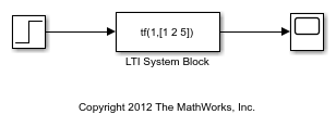
The LTI System block imports linear system model objects into the Simulink® environment. You specify the LTI model to import in the LTI system variable parameter. You can import any type of proper linear time-invariant dynamic system model. If the imported system is a state-space (ss) model, you can specify initial state values in the Initial states parameter.
Examples

Ports

Input

expand all

For a single-input LTI system, the input signal is a scalar. For multiple-input systems, combine the system inputs into a vector signal, using blocks such as:

Output

expand all

For a single-output LTI system, the output signal is a scalar. For multiple-output systems, the output signal is a vector. To split system outputs into scalar signals, use blocks such as:

Parameters

expand all

Specify the linear system for the block as a MATLAB® expression or a variable in the MATLAB workspace, the model workspace, or a data dictionary. The model can be SISO or MIMO.

Most linear time-invariant dynamic system models are supported, except:

  • Frequency-response data models, such as frd and genfrd models.

  • Nonlinear identified models, such as idnlarx.

  • Models with unmodeled dynamics, such as udyn.

The specified model must be proper (see isproper).

The model can be either continuous time or discrete time. When the LTI system block is in a Simulink model with synchronous state control (see the State Control (HDL Coder) block), you must specify a discrete-time model.

Simulink converts the model to its state-space equivalent prior to initializing the simulation.

If the linear system is in state-space form, specify the initial state values as a vector with as many entries as the system has states. If you specify a scalar value, the block applies that value to each state in the system. The default value, [], initializes all states to zero.

The concept of initial state is not well-defined for linear systems that are not in state-space form, such as transfer functions or zero-pole-gain models. For such models, the initial state depends on the choice of state coordinates used by the realization algorithm. As a result, the block ignores this parameter for such models.

Set the order of the Pade approximation for linearization routines.

  • The default value is 0, which results in a unity gain with no dynamic states.

  • Setting the order to a positive integer n adds n states to your model, but results in a more accurate linear model of the delay.

Use a vector of positive integers to specify a different order for each input channel.

Extended Capabilities

C/C++ Code Generation
Generate C and C++ code using Simulink® Coder™.

Version History

Introduced before R2006a

expand all