GMSK Modulator Baseband
Modulate signal using Gaussian minimum shift keying method
Libraries:
Communications Toolbox /
Modulation /
Digital Baseband Modulation /
CPM
Description
The GMSK Modulator Baseband block modulates an input signal using the Gaussian minimum shift keying (GMSK) method. The output is a baseband representation of the modulated signal. For more information about the modulation and the filtering applied, see Algorithms.
Examples
The cm_gmsk_vs_msk model compares Gaussian minimum shift keying (GMSK) and minimum shift keying (MSK) modulation schemes.

The Random Integer Generator block provides a source of uniformly distributed random integers in the range [0, M-1], where M is the constellation size of the GMSK or MSK signal. The Unipolar to Bipolar Converter block maps a unipolar input signal to a bipolar output signal consisting of integers between -(M-1) and +(M-1). The bipolar data is routed to separate paths. The top path applies GMSK modulation by using the GMSK Modulator Baseband block. The bottom path applies MSK modulation by using the MSK Modulator Baseband block. Noise is added to both the GMSK and MSK signals by using AWGN Channel blocks. The Eye Diagram blocks are used to visualize eye diagrams of both signals.
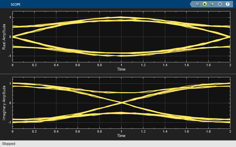
The eye diagrams show the similarity between the GMSK and MSK signals when you set the initial pulse length of the GMSK Modulator Baseband block to 1.


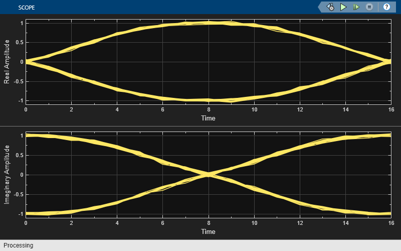
To view the difference that a partial response modulation has on the eye diagram, set the initial pulse length in the GMSK modulator to 5. The increased pulse length results in an increase in the number of paths, showing that the CPM waveform depends on values of the previous symbols as well as the present symbol. Plot the eye diagram of the GMSK signal.

If you change the initial pulse length to an even number, such as 4, you should set the initial phase offset of the GMSK modulator to pi/4 and the offset argument of the eye diagram to 0 for a better view of the modulated signal. To more clearly view the Gaussian pulse shape, you must use scopes that enable you to view the phase of the signal, as described in the View CPM Phase Tree Using Simulink example.

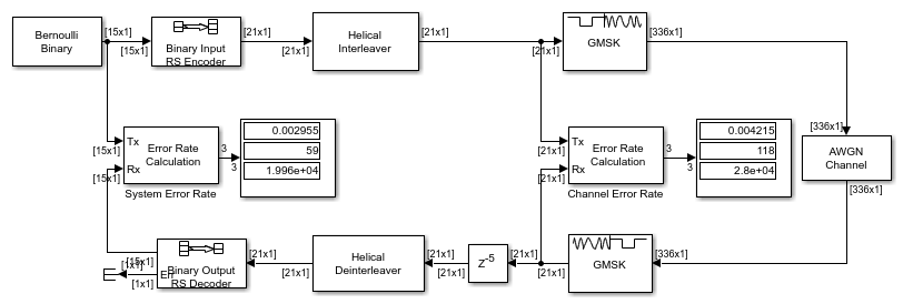
Demodulate a GMSK-modulated signal impaired by AWGN and compute the bit error rate.
The cm_gmsk_mod_demod model generates random Bernoulli distributed binary data and then applies GMSK modulation to frames data. The GMSK-modulated signal passes through an AWGN channel and then is demodulated by using the GMSK method. The bit error rate is calculated on frames of data.
The Error Rate Calculation block has the receive delay set to the value of the traceback depth used by the GMSK Baseband Demodulator block. The model uses the Find Delay block to confirm the delay equals the value of the traceback depth.

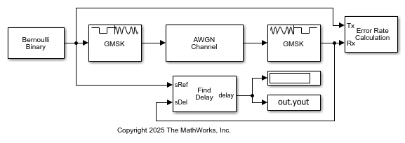
Transmit to receive delay is 16 symbols. BER = 8.3934e-05
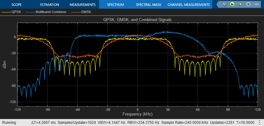
Combine two 60 KHz frequency bands adjacent to each other.
Run the model to explore how combining the frames affects the signals. The model frequency shifts and combines frames of QPSK and GMSK baseband modulated signals. A spectrum analyzer displays the individual and combined signals.


Extended Examples
Soft Decision GMSK Demodulator
A system that includes convolutional coding and GMSK modulation. The receiver in this model includes two parallel paths, one that uses soft decisions and another that uses hard decisions. The model computes bit error rates for the two paths to illustrate that the soft decision receiver performs better. The performance advantage for soft decision reception over hard decision reception is expected because soft decisions enable the system to retain more information from the demodulation operation to use in the decoding operation.
Correct Misalignment of Interleaved Words Due to Demodulation
In communications systems, you can use techniques such as interleaving to protect against burst errors. Interleaving is a process that rearranges the order of data bits or symbols. The effectiveness of interleaving depends on the precise alignment of data words prior to this process. This example shows how to correct for the misalignment of codewords due to delays incurred in digital demodulation, when performing deinterleaving and outer block decoding.
Ports
Input
Input signal, specified as a scalar or column vector. For more information, see Integer-Valued Signals and Binary-Valued Signals.
This port is unnamed on the block.
Data Types: double | Boolean | int8 | int16 | int32
Output
GMSK-modulated baseband signal, returned as a column vector. Use the Output data type parameter to specify the output data type. The modulated output symbols are oversampled by the Samples per symbol parameter value. For information on the processing rates, see Single-Rate Processing and Multirate Processing.
This port is unnamed on the block.
Data Types: double | single
Parameters
To edit block parameters interactively, use the Property Inspector. From the Simulink® Toolstrip, on the Simulation tab, in the Prepare gallery, select Property Inspector.
Integer or group-of-bits input indicator, specified as
Integer or Bit.
Set this parameter to
Integerto input data as integers.Set this parameter to
Bitto input data as bits.
For more information, see Integer-Valued Signals and Binary-Valued Signals.
Product of the bandwidth and symbol time of the Gaussian pulse shape, specified as a positive scalar. For more details, see Algorithms.
Length of the frequency pulse shape, specified as a positive integer. This parameter represents the truncated frequency pulse length of the Gaussian pulse shape in symbol intervals.
Symbol prehistory, specified as -1,
1, or a vector with elements equal to those values.
This parameter defines the data symbols that the modulator uses before the
block processes symbols, in reverse chronological order.
A scalar value expands to a vector of length LP – 1. LP represents the pulse length, which is specified by the Pulse length (symbol intervals) parameter.
For a vector, the length must be LP – 1.
Initial phase offset of the modulated waveform in radians, specified as a scalar.
Number of samples per output symbol, specified as a positive integer. The number of samples per symbol represents the upsampling factor from input samples to output samples. For more information, see Signal Upsampling and Rate Changes.
Block processing rate, specified as one of these options:
Enforce single-rate processing— The input and output signals have the same sample time. The block implements the rate change by making a size change at the output when compared to the input. The output width equals the product of the number of symbols and the Samples per symbol parameter value.Allow multirate processing— The input and output signals have different sample times. The output sample time equals the symbol period divided by the Samples per symbol parameter value.
Data type of the output, specified as double or single.
Block Characteristics
Data Types |
|
Multidimensional Signals |
|
Variable-Size Signals |
|
More About
This block accepts a scalar or column vector input signal. For a column vector input signal, the width of the output equals the product of the number of symbols and the value for the Samples per symbol parameter.
When you set the Input type parameter to
Integer, the block accepts bipolar values of–1and1.When you set the Input type parameter to
Bit, the block accepts binary values of0and1.
In single-rate processing mode, the input and output signals have the same port sample time. The block implicitly implements the rate change by making a size change at the output when compared to the input. In this mode, the input to the block can be multiple symbols. The output width equals the product of the number of input symbols and the Samples per symbol parameter value.
In multirate processing mode, the input and output signals have different port sample times. In this mode, the input to the block must be one symbol. The output sample time equals the symbol period divided by the Samples per symbol parameter value.
The group delay is the number of samples between the filter response start and the filter response peak. This block introduces a group delay equal to (LP/2) ×NSPS. The Pulse length (symbol intervals) parameter specifies the pulse length, LP, and the Samples per symbol parameter specifies NSPS using a reference of output sample periods. The traceback depth for the Viterbi algorithm at the receiver (demodulator) is specified by the Traceback depth parameter. In most cases, the traceback depth is larger than the group delay. The traceback depth of the demodulator determines the net delay effect.
Algorithms
GMSK is a continuous phase (CPM) scheme with no phase discontinuities because the frequency changes occur at the carrier zero-crossing points. For more information, see [1]. For GMSK (and MSK), the frequency difference between the logical one and logical zero states is always equal to half the data rate. This difference can be expressed in terms of the modulation index. Specifically, an input symbol of 1 causes a phase shift of π/2 radians, which corresponds to a modulation index of 0.5. GMSK applies a Gaussian Pulse Shaping Filter.
These equations define the frequency pulse shape of the Gaussian pulse shaping filter:
Bb represents the bandwidth of the pulse and T is the symbol durations. Q(t) is the complementary cumulative distribution function.
The BT product parameter represents the bandwidth multiplied by time. Use this parameter to reduce the bandwidth at the expense of increased intersymbol interference. The Pulse length (symbol intervals) parameter measures the length of the Gaussian pulse shape in symbol intervals.
References
[1] Anderson, John B., Tor Aulin, and Carl-Erik Sundberg. Digital Phase Modulation. New York: Plenum Press, 1986.
Extended Capabilities
C/C++ Code Generation
Generate C and C++ code using Simulink® Coder™.
Version History
Introduced before R2006a
See Also
Blocks
- GMSK Demodulator Baseband | CPM Modulator Baseband | CPFSK Modulator Baseband | MSK Modulator Baseband
Objects
MATLAB Command
You clicked a link that corresponds to this MATLAB command:
Run the command by entering it in the MATLAB Command Window. Web browsers do not support MATLAB commands.
Select a Web Site
Choose a web site to get translated content where available and see local events and offers. Based on your location, we recommend that you select: .
You can also select a web site from the following list
How to Get Best Site Performance
Select the China site (in Chinese or English) for best site performance. Other MathWorks country sites are not optimized for visits from your location.
Americas
- América Latina (Español)
- Canada (English)
- United States (English)
Europe
- Belgium (English)
- Denmark (English)
- Deutschland (Deutsch)
- España (Español)
- Finland (English)
- France (Français)
- Ireland (English)
- Italia (Italiano)
- Luxembourg (English)
- Netherlands (English)
- Norway (English)
- Österreich (Deutsch)
- Portugal (English)
- Sweden (English)
- Switzerland
- United Kingdom (English)

