Main Content

Unipolar to Bipolar Converter

Map unipolar signal in range [0, M – 1] to bipolar signal

  • Unipolar to Bipolar Converter block

Libraries:
Communications Toolbox / Utility Blocks

Description

The Unipolar to Bipolar Converter block maps the unipolar input signal to a bipolar output signal.

Examples

expand all

Use the Unipolar to Bipolar Converter to remap a signal from unipolar to bipolar.

The cm_convert_unipolar2bipolar model converts signals from unipolar to bipolar and displays the bipolar mapping.

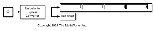
With Output data type set to Inherit via internal rule, vary the M-ary number and Polarity settings, run the simulation, and then display the output of the Unipolar to Bipolar Converter block.

For the input signal int8([0; 1; 2; 3]),
 With Polarity = Positive and M-ary number = 4:
  The output is -3 -1  1  3, and type is int8.
 With Polarity = Negative and M-ary number = 4:
  The output is 3  1 -1 -3, and type is int8.
With Polarity = Positive and M-ary number = 2^7:
  The output is -127 -125 -123 -121, and type is int8.
 With Polarity = Positive and M-ary number = 2^7+1:
  The output is -128 -126 -124 -122, and type is int16.

Ports

Input

expand all

Input signal, specified as a scalar, vector, or matrix. The block expects input integers in the range [0, (M – 1)], where M is the M-ary number parameter.

The input signal is unnamed on the block mask.

Data Types: single | double | int8 | int16 | int32

Output

expand all

Output signal, returned as a signal of integers in the range [–(M – 1), (M – 1)] with the same dimensions as the input signal, In. M is the M-ary number parameter value. The Output data type parameter specifies the desired data type.

  • When you set M to an even integer, the block outputs odd integer values.

  • When you set M to an odd integer, the block outputs even integer values.

The output signal is unnamed on the block mask.

Note

The output might not be valid for unsigned integer input values, noninteger input values, or integer input values outside the range [0, (M – 1)].

Parameters

expand all

To edit block parameters interactively, use the Property Inspector. From the Simulink® Toolstrip, on the Simulation tab, in the Prepare gallery, select Property Inspector.

Number of symbols in the bipolar or unipolar alphabet, specified as a positive integer.

Relative ordering of symbols, specified as Positive or Negative.

  • Positive causes the block to maintain the relative ordering of symbols in the alphabets.

  • Negative causes the block to reverse the relative ordering of symbols in the alphabets.

This value of this parameter determines the output for input value k and M-ary number parameter value M.

 Output
Positive 2k – (M – 1)
Negative –2k + (M – 1)

Output data type of the bipolar signal, specified as Inherit via internal rule, Same as input, double, int8, int16, or int32.

When you set this parameter to Inherit via internal rule, the block determines the output data type based on the input data type as follows:

  • If the input data type is either single or double, the output data type is the same as the input data type.

  • If the input data type is not single or double:

    • For the M-ary number parameter value, M, the block computes the ideal signed integer output word length, ideal_word_length, required to contain the range [–(M – 1), (M – 1)] as:

      ideal_word_length = ceil(log2(M)) + 1, where + 1 fulfills the need for the sign bit.

    • The block sets the output data type to be a signed integer, based on the smallest word length (in bits) that can best fit the computed ideal word length.

Note

Selections in the Hardware Implementation Pane (Simulink) that constrain word length do not affect how this block determines output data types.

Block Characteristics

Data Types

Boolean | double | fixed point | integer | single

Multidimensional Signals

no

Variable-Size Signals

no

Extended Capabilities

expand all

C/C++ Code Generation
Generate C and C++ code using Simulink® Coder™.

Version History

Introduced before R2006a