Working with Digital Inputs and Outputs on STM32 Using Simulink
From the series: Getting Started with STM32 Nucleo Boards Using Simulink
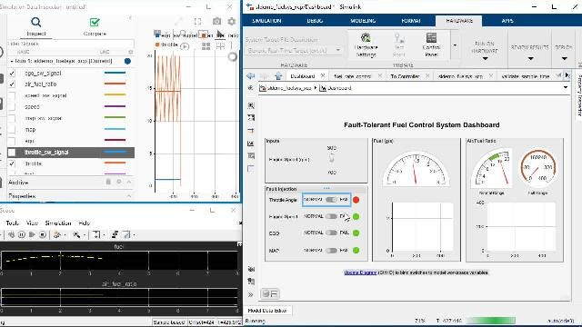
Follow a step-by-step guide on how to design a model in Simulink® using the digital input and output ports on a STM32 Nucleo board. It includes an example of how to make the onboard user LED blink as well as how to use the onboard Push Button to toggle the LED. It also explains the concepts of connected IO and external mode connection with the hardware using Model-Based Design.
To learn more about how to install Simulink Coder Support Package for STMicroelectronics Nucleo Boards watch:
Install Simulink Coder Support Package for STM32 Nucleo Boards (2:25)
Published: 5 Jul 2022
Select a Web Site
Choose a web site to get translated content where available and see local events and offers. Based on your location, we recommend that you select: .
You can also select a web site from the following list
How to Get Best Site Performance
Select the China site (in Chinese or English) for best site performance. Other MathWorks country sites are not optimized for visits from your location.
Americas
- América Latina (Español)
- Canada (English)
- United States (English)
Europe
- Belgium (English)
- Denmark (English)
- Deutschland (Deutsch)
- España (Español)
- Finland (English)
- France (Français)
- Ireland (English)
- Italia (Italiano)
- Luxembourg (English)
- Netherlands (English)
- Norway (English)
- Österreich (Deutsch)
- Portugal (English)
- Sweden (English)
- Switzerland
- United Kingdom (English)
Asia Pacific
- Australia (English)
- India (English)
- New Zealand (English)
- 中国
- 日本Japanese (日本語)
- 한국Korean (한국어)