Using Simulink with STM32 Discovery and STM32F4xx-Based Boards - MATLAB & Simulink
Video Player is loading.
Current Time 0:00
Duration 6:15
Loaded: 0%
Stream Type LIVE
Remaining Time 6:15
 
1x
  • Chapters
  • descriptions off, selected
  • en (Main), selected
    Video length is 6:15

    Using Simulink with STM32 Discovery and STM32F4xx-Based Boards

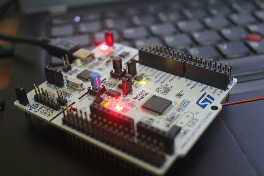
    Deploy a Simulink® model to blink the onboard LED on an STM32 Nucleo F401RE board using the Embedded Coder™ Hardware Support Package for STMicroelectronics® STM32 Discovery and STM32F4xx processor-based boards.

    Published: 21 Nov 2021

    Hello, everyone. In this getting started video, I will show you how to use the Embedded Coder Support Package for STMicroelectronics Discovery Boards to an example.

    [MUSIC PLAYING]

    In this example, we'll use 401RE ST Nucleo board. And we will start by blinking the onboard LED for a set period and extend it to use the onboard push button to control the LED. Let us begin by opening MATLAB. This video assumes that you have the Embedded Coder Support Package already installed.

    From the MATLAB 2021 B release, we have deeper support for the F4 family of processors. And this differentiates from the basic support that we provide with the Nucleo support package. Let me create a new model in the desired folder. Let me call it blinkLED. Before I start modeling, let me go to the configuration parameters by using the shortcut Control plus E.

    I'm going under Hardware Implementation. Let we choose the F4 Based volts. The first thing I need to do is either browse to an existing STM32CubeMX project file that I have for the same processor. Or I can create a new one. Let me show you the process of creating a new file first.

    Clicking on Create, let me give a name for the STM32CubeMX project. And we need to choose the hardware that we'll be using. In my case, I'm using a NUCLEO-F401RE board that I've selected here. Clicking on Apply begins the process of creating a new STM32CubeMX project.

    Now we can click on OK. Next, clicking on Launch will open the CubeMX project that we just created. In case you're new to the CubeMX tool, there are good online resources that will help you get started with the interface of the tool. Here within CubeMX, the first aspect of my example is to blink the onboard LED, which is connected to PA5. It has already set the GPIO_Output, which is what we need.

    You can further verify the details here. In case you have an existing CubeMX mixed project that you're importing into Simulink, there are additional configurations that you need to ensure. Going under the Project Manager tab and under Project, ensure that Do not generate the main is enabled and Generate Under Root is disabled

    Additionally, within the Advanced Settings tab, ensure that low-level drivers are selected for the peripherance, and they Do Not Generate Function Call, and Visibility and Static are disabled. Going back to Simulink, let's click on Apply and close this. We can open the library browser by doing a Control-Shift-L. And under our support package, going to the F4 Based boards, we have our Digital Port Write block that we can drag it into our model. Let's set the PIN number as 5 of the GPIO port.

    Next we can bring in a Pulse Generator block. And then to connect these two. Going into the block parameters of the Pulse Generator, let me make it Sample Based with a Period of 2. Setting a Sample Time of 0.5, should link the LED every 0.5 seconds. Let's do an Apply. Now we can either choose to do a Monitor & Tune or directly Build and Deploy onto the hardware.

    Before we do that, let's go back to the Configuration Parameters. And under the Connectivity tab, for this particular hardware, it is the USART2, an engine within CubeMX that is set to Asynchronous mode. For the Serial port, we can go to the Device Manager to find the component of the connected device. In my case, it is COM17.

    Let's do an Apply. Click on OK. Now we are ready to deploy our model to the hardware. Let me change simulation time during flight and running Monitor & Tune. Now that the code is running on the hardware, we can see the LED blinking every 0.5 seconds.

    Extending this example, next here, just try to use the onboard push button to control the LED. Let me delete the Pulse Generator block, and add in Digital Port Read block, and connect these two blocks together. The onboard push button is connected to GPIO port C on Pin number 13.

    Let's open the Configuration Parameters. Then within the Configuration Parameters, we need to launch the STM32CubeMX project to set the GPIO of the push button. The port, PC13, is already set as the GPIO input. Let's Save the project and close it. Let's do an Apply. Learning this model.

    Now that the model is running, you can see the status of the LED changing with the press of the button. Let me show you the use of a Display block to show the status of the push button. But before we run the model on Monitor & Tune, we need to go back to the Configuration Parameters and under External mode, ensure that you Use a Dedicated Timer to Improve Time Stamp Accuracy is disabled. That option needs to be disabled to see the data when you do a Monitor & Tune.

    Now that the model is deployed, we can see that with the push of a button, the LED status changes. We are able to see the GPIO port-- the Display block within Simulink. That concludes the getting started video. Further to this, there are other examples that you can try from our Documentation page, including the Hardware Interrupt block or an ADC block.

    View more related videos