Fuzzy Logic Examples | Fuzzy Logic, Part 3
From the series: Fuzzy Logic
Brian Douglas, MathWorks
Watch this fuzzy logic example of a fuzzy inference system that can balance a pole on a cart. You can design a fuzzy logic controller using just experience and intuition about the system—no mathematical models necessary.
Published: 14 Sep 2021
In the last two videos, we walked through how a fuzzy inference system works in general. And so, in this video, we’re going to take that knowledge and show one way to design a fuzzy inference system. And to do that we’ll develop a fuzzy inference-based controller that can balance a pole on a cart. I want to show you how a fuzzy logic controller can be designed using just experience and intuition about the system - no mathematical models necessary. I think you’ll be surprised at how simple it is to set up if you have a good understanding of how your system behaves. So, I hope you stick around for it. I’m Brian, and welcome to a MATLAB Tech Talk.
This is the cart/pole problem. It’s a pretty standard academic example so I thought it would be nice to use an example that you may already know how to solve using other control methods. It works like this. The pole is being pulled down by the constant force of gravity and is free to rotate about this pivot point. The cart can roll back and forth and we can apply an external force to accelerate the cart left and right. We have four states that we are measuring: pole angle and angular velocity and cart position and velocity. And if you want to try to copy this example, these are the physical parameters of the this particular system.
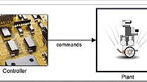
Ok, so the overall block diagram looks like this. Force enters the cart/pole dynamic system, and the four state variables come out. Then a fuzzy logic controller uses one or more of the output variables to determine the appropriate force that keeps the pole upright. Simple enough, right?
Well, let’s head over to Simulink and start the design. I’ve already put a few blocks in this Simulink model. This block is the dynamics of the cart and pole system which you can see takes the cart force as input and outputs the four states. The pole initializes perfectly balanced and since there are no other external disturbances in this model, I disturb it by injecting a small impulse at time = 1 second just to get the cart moving a bit and get the pole to fall over. This block over here brings up the animation so that we can see what the system is doing more easily than looking at a plot.
So let’s start this and see what happens. The cart and pole start perfectly balanced, and then the impulse gets the system moving, and the pole falls and loops around and around and around. I forgot to mention that there is no damping in this system and so the pole will never come to rest. Alright, that was fun but now let’s design a system to control it.
If I had a model of the cart and pole system, then I could use something like full state feedback and a tuning technique like LQR to design a controller. But for this example, let’s assume I don’t have this model and that generating a reliable and accurate model would be difficult. This is one of the situations where using your experience with the system and a fuzzy logic-based controller can be beneficial. So, let’s walk through how that would work.
This left screen is a MATLAB live script where I’ll design the fuzzy inference system, and then once it’s created, I’ll pull it over in to Simulink to test it out. So, to begin I’ll create a mamdani fuzzy inference object with the mamfis function. I need to specify the number of inputs and outputs and the number of membership functions for each. Now, ultimately we’ll probably want to use all 4 inputs, pole angle and angular velocity, and cart position and velocity. However, I want to start off really simply but just seeing if we can balance the pole using just the pole angle. Intuitively, it makes sense that if the pole is leaning to one side you should be able to move the cart in the same direction, and get it under the pole, to push it back up. That’s the idea anyway.
So, in this case there is only one input. And to keep everything really simple, I’ll also only define two membership functions as well.
The input is pole angle, theta, and the range of this input is between -pi and pi radians. However, even though the input could be anywhere in this range, I’m going to set up this system to just try to keep the angle between plus and minus 0.5 radians.
The way I’m going to do that is with the input membership function shape. I’m choosing a z shape for the negative membership function because it saturates at 100% membership below this specified lower bound which is negative .5 radians in this case, and then smoothly ramps down to 0% membership at 0.5 radians. And for the positive membership function, I’m using an s shape which does the opposite.
You know what, I’ll plot it here so you have an idea of what they look like.
You can see the saturation occurring outside of plus minus 0.5 radians and, if I zoom in, you can see how the two membership functions overlap over the range that I’m concerned with. The way we can read this is that if theta is 0, or the pole is perfectly balanced, then that value belongs equally to the negative and positive membership functions. Otherwise, the degree of membership is skewed more negative or more positive depending on theta.
If I had just defined these membership functions between plus minus 0.5 radians, then this controller would not produce a response if the pole happens to fall outside of that range. But by defining the functions across the entire input range of plus minus pi, we guarantee that the controller will still label the input as fully negative or positive.
I’ll define the output in a similar way but this time I’ll define the membership function shapes as a generalized bell function. I don’t need these functions to saturate and extend to some unknown and arbitrarily large value since I know what force this actuator is capable of delivering. Also, I know how much force I want to apply to the cart and so I’ll situate these bell shapes within that range of about 12 Newtons in either directions.
I’m going to call them NM for negative medium, and PM for positive medium. The reason I’m calling these medium is that, spoiler alert, later I’m going to add larger and smaller membership functions to the output, and I want to keep the names consistent. But for now, we just have these two possible memberships.
So theta can be either positive or negative and the resulting force can be either positive medium or negative medium. Now we can define the rules for inference. And with such a simple system we only need two rules! If theta is negative then force is negative medium, and if theta is positive then force is positive medium. These rules basically encode the intuition that we had earlier, that is to balance the pole we need to move the cart in the direction it’s leaning.
Remember, this is the kind of experience and intuition you might have from just trying to balance a pole yourself, there is no need for a mathematical model to make this kind of inference.
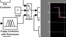
Ok, so once we add these rules to our fuzzy inference system we’re done with the design, and we can pull it into Simulink with a Fuzzy Logic Controller block. The output of the controller is cart force and I can add it to the impulse disturbance and feed back the variable theta. And that’s it, we have our one input and one output and we’re ready to run it.
Ooh, look at it go! It’s definitely keeping the pole upright but it’s doing sort of a wiggle dance as the cart keeps trying to go under the pole but the momentum of the pole causes an overshoot and the cart has to come back, causing another overshoot, ad naseum.
Once again we can come back to our intuition and experience with the problem and realize that if we take into account the pole angular velocity and not just the angle then we can use that to help slow the pole rotation down right as it reaches the balance point.
So, back over at the live script I’m going to change the number of inputs to 2, and add a second input for theta dot. I’ll keep the same membership function shapes but change the input range to plus and minus 5 rad/s to account for quick rotations.
Now as for the output, I think that I want to really restrict the angular velocity of the pole by using a large force whenever motion is observed. I don’t want the pole to rotate too quickly ever, so what I’m going to do is add two more membership functions to the output and make them centered around a larger force. I’ll call them negative large and positive large. And this is what these membership functions look like. So, the same as medium, just moved over a bit.
Now I can add two more rules to our inference system. If theta dot is negative then force is negative large. That is, if the pole is rotating in the negative direction, really try to stop that rotation by moving the cart with a large negative force. And the opposite for a positive theta dot.
I want to let you know that the way I’m setting up these rules where there is one input per rule isn’t typical for a fuzzy inference system. I’m just doing it this way because I feel is helps tell the story about how each of the inputs contribute to the overall controller. Usually, you would want to set up this up so that every rule contains all of inputs and’ed together. For example, in this case, I’d still have four rules, but they would look like the following. Setting up the rules in this way actually gives you more flexibility in the design than how I’m doing it in the video. However, again, for simplicity and clarity we’re going to stick with these rules where there is just a single input per rule.
Ok, so let’s give this version of the controller a shot. This has two inputs so I need to mux together theta and theta dot and send both of them into the fuzzy logic controller. Otherwise, everything else is exactly the same. Now, let’s run this model.
Oh, look at that! The pole is perfectly balanced. It’s rock solid since the cart is moving quickly to stop any possible pole movement. This looks good … well except for the fact that the cart is ever so slightly wandering away as it tries to balance this pole. That will not do. So, let’s use the cart position and the cart velocity to stop this motion.
I’m going to zip through this section pretty quickly since it’s just more of the same. I’m adding two new inputs with their own two z and s shaped membership functions. And I’m going to add two more membership functions to the output, negative small and positive small.
If we look at the plot of the output functions we can talk about why I made these so much more narrow. My thought is that since the cart is only slightly wandering away, I didn’t want to push it back with a lot of force, possibly disrupting the balance of the pole. So I think that just by ever so slightly nudging it we’ll be able to keep the pole nicely balance and still be able to hold the cart steady.
So, with that logic, I’m adding two more rules that move the cart slightly in the opposite direction of the position error, and then to keep the velocity of the cart low, I’m adding two more rules that try to maintain zero velocity with a medium amount of force. It’s not obvious at first why I’m moving the cart further away from the zero position point but here is my reasoning. If the the pole is perfectly balanced, I want the cart to first move away to rotate the pole toward the goal position. This will trigger the rule that tries to keep the pole upright by moving the cart with a greater force in the opposite direction. In this way, the cart ultimately moves in the direction I want by nudging it the other way first.
Ok, so with the controller ready we need to make some updates on the Simulink side. Let’s give this controller a target position to follow. I’ll change the signal generator block to output a square wave with amplitude 1. This is the target position that will jump back and forth. And then I’ll subtract the measured position from it to produce a position error which is what the fuzzy logic controller will try to drive to 0. We then have to add position error and velocity to our mux and input all four variables into our fuzzy logic controller. So, let’s run this final version and see how it does.
Way cool, how awesome is that? I mean it’s a bit slow, so I could spend some time tweaking the rules and membership functions, but for this video I think it shows the result of a fuzzy inference system quite nicely. And as we showed, we didn’t need to derive the model of the cart / pole system. We were able to develop this controller using experience about the system and our intuition about how to control it.
Now, I wrote code to design the fuzzy controller because I think it’s easier to follow along in video format, however, all of this code could have be bypassed and the design could be done graphically using the fuzzy logic designer app. With the app, there is a click and drop interface where you could design the membership functions and the rules. Plus it allows you to visualize the rules which can make it easier to troubleshoot and tweak the controller.
So, if you want to develop a fuzzy inference system you can choose your preference of what you like to use as an interface whether it’s graphical or written code.
Ok, lastly, I want to remind you that fuzzy interference systems have a lot of practical applications and have been used in many different industries. We already know that we can develop a fuzzy logic controller which can take the place of other traditional control methods.
Another example of this is within autonomous driving where a fuzzy logic controller has been developed that can automatically park a car. This system uses range sensors on all four sides to guide the car into the empty spot. This is a really interesting example because the car has nonholonomic constraints. Basically that means that there are more degrees of freedom for the car than there are possible ways to move it. For example, the car cannot directly move sideways but instead must make a series of other motions to go in that direction. And this is intuitive to a human driver and therefore can be a great candidate for a fuzzy logic-based controller.
Another famous example is the speed controller for the Sendai Subway system in Japan. Using a fuzzy logic controller, the engineers were able to make smoother starts and stops as well as be 10% more energy efficient than human controlled acceleration.
However, we also talked about in earlier videos how fuzzy inference system can be used for decision processes not just controllers. In the second video we talked about a loan risk example and it turns out that there are many practical examples of fuzzy inference decision systems in the field of finance.
There are also some really interesting examples in the medical industry. In fact, one in particular is the use of fuzzy logic to control an artificial pancreas. Researches show that fuzzy logic is a viable alternative to other model-based controllers for a closed-loop insulin delivery system because it "does not require differential equations of the glucoregulatory system and allows clinicians to personalize dosing aggressiveness to meet individual patient requirements.
This is actually a really interesting problem and we’re going to dive into a version of an artificial pancreas in the next video. So, in this video, we covered how to design a fuzzy inference system from experience, but in the next video, using the artificial pancreas example, we’ll show how to design a system when you have a lot of data.
So, if you don’t want to miss that or any other future Tech Talk videos, don’t forget to subscribe to this channel. Also, if you want to check out my channel, Control System Lectures I cover more control theory topics there as well. Thanks for watching and I’ll see you next time.


