Rate-Compatible LDPC Encoder and Decoder
This example shows how to design and verify a rate-compatible low-density parity-check (RC-LDPC) encoder and decoder for a custom communication system that is suitable for HDL code generation.
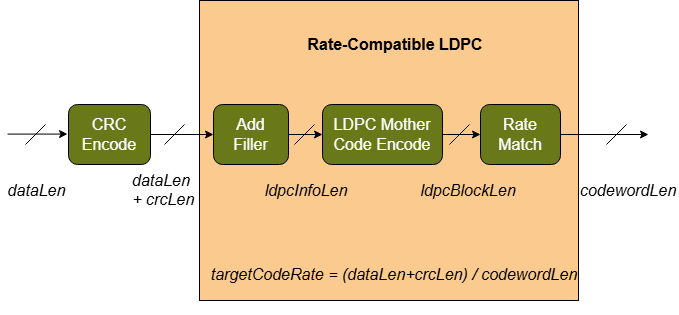
The RC-LDPC encoder and decoder implement three mirrored processing steps. Each step aims to mitigate the impact of different error classes on the system performance.
Cyclic Redundancy Check (CRC): The CRC step provides error detection capabilities. If the LDPC fails to correct all bit errors, then the CRC can detect that the received bits are incorrect. You can use this check to discard invalid data and schedule retransmission. The encoder computes and concatenates CRC bits to the data bits, and this outer code forms the information bits for the RC-LDPC step. The decoder checks the information bits from the RC-LDPC decoder by recomputing the CRC bits from the received data bits and comparing it to the received CRC bits. The decoder reports the error in the event of a mismatch. For more information on CRC codes see Cyclic Redundancy Check Codes.
RC-LDPC: The RC-LDPC step provides error correction capabilities. The LDPC code can correct bit errors in the received data to achieve performance near the Shannon limit. The basis of the RC-LDPC is an LDPC mother code, which defines fixed information length, code word length, and code rate parameters. The rate compatibility provides flexibility around the mother code parameters, allows for dynamic code rate and codeword length selection to adapt to channel conditions and system requirements. Rate compatibility implements a combination of shortening, puncturing, and repetition techniques. The encoder encodes information bits using the LDPC mother code to create the LDPC codeword. Then the encoder rate matches the LDPC codeword to achieve the specified rate and codeword length. The decoder rate-recovers soft-decision log-likelihood-ratio (LLR) samples to create the received LDPC codeword. Then the decoder decodes the hard decision information bits using the LDPC mother code. For more information on LDPC codes, see LDPC Codes.
Block Interleaving: The block interleaving step improves codeword performance in practical wireless channels. In a wireless channel, bit errors tend to cluster due to burst interferers in single carrier systems, and channel nulls in multicarrier systems. LDPC codes achieve the best performance when bit errors are uniformly distributed throughout the codeword. To mitigate the effects of burst errors on decoder performance, the block interleaver spreads adjacent codeword bits across modulated symbols to maximize the distance of bits mapped to a symbol. The block interleaver consists of a matrix with number of rows equal to the number of bits per symbol, and number of columns equal to the codeword length divided by the number of columns. The encoder writes the codeword bits into the interleaver matrix row by row, and reads bits out column by column to form the output. The decoder writes the received LLRs into the interleaver matrix column by column, and reads bits out row by row to form the input to the RC-LDPC. For more information on block interleavers, see Block Interleaving.
The encoder and decoder designs both have a MATLAB® reference and a Simulink® model. The MATLAB reference explores the design space and provides test vectors. The Simulink model simulates the fixed-point and latency behavior and generates HDL code.
You can use this example to integrate forward error correction (FEC) into a custom communications system, such as the Introduction to Custom OFDM example or the QPSK Transmitter and Receiver example.
Coding Scheme Definition
Define the coding scheme with design-time constants for each step of the algorithm. These constants define the core performance of the coding scheme and configure the hardware implemented. The values cannot be modified after code generation. These constants also define the ranges of values supported for the tunable codeword properties, which can be modified at run time.
CRC: Specify the generator polynomial used to compute the check bits,
crcPoly. The length of this polynomial defines the number of bits used for the CRC. Increasing the CRC length lowers the probability of false positives in the CRC decoder but decreases the peak throughput due to the overhead of transmitting additional non-data bits. The length of the CRC is equal to the length ofcrcPolyminus 1. The example uses a default CRC polynomial ofz^24 + z^23 + z^14 + z^12 + z^8 + 1. The behavior of the CRC cannot be modified at runtime.RC-LDPC: Specify the LDPC mother code used by the core of the coding algorithm. The LDPC mother code must be defined by a quasi-cyclic prototype matrix,
qcProto, and a block size,blockSize. The example generates the full parity check matrix from these parameters and defines the length of the codeword,N, and the number of information bits,K, with rateK/N. The example uses arate = 1/2, (N,K) = (1296,648)mother code. You can modify the final codeword parameters at runtime by specifying the number of data and codeword bits. The maximum length of the codeword at runtime is specified bymaxCodewordLen.Block Interleaving: Specify the maximum number of interleaver rows,
maxIntlvRows. The number of interleaver rows can be modified at runtime to change the interleaver pattern.
This code defines the coding scheme definition for the CRC, LDPC, and block interleaving.
%% Define RC-LDPC Constants

% CRC design
% Use CRC-24 with polynomial z^24 + z^23 + z^14 + z^12 + z^8 + 1
crcPoly = [1 1 zeros(1,8) 1 0 1 zeros(1,3), 1 zeros(1,7) 1];

crcLen = length(crcPoly)-1;
crcCfg = crcConfig("Polynomial",crcPoly);

% LDPC design
% Use rate = 1/2, (N,K) = (1296,648) QC-LDPC mother code
qcProto = [
    40 -1 -1 -1 22 -1 49 23 43 -1 -1 -1  1  0 -1 -1 -1 -1 -1 -1 -1 -1 -1 -1
    50  1 -1 -1 48 35 -1 -1 13 -1 30 -1 -1  0  0 -1 -1 -1 -1 -1 -1 -1 -1 -1
    39 50 -1 -1  4 -1  2 -1 -1 -1 -1 49 -1 -1  0  0 -1 -1 -1 -1 -1 -1 -1 -1
    33 -1 -1 38 37 -1 -1  4  1 -1 -1 -1 -1 -1 -1  0  0 -1 -1 -1 -1 -1 -1 -1
    45 -1 -1 -1  0 22 -1 -1 20 42 -1 -1 -1 -1 -1 -1  0  0 -1 -1 -1 -1 -1 -1
    51 -1 -1 48 35 -1 -1 -1 44 -1 18 -1 -1 -1 -1 -1 -1  0  0 -1 -1 -1 -1 -1
    47 11 -1 -1 -1 17 -1 -1 51 -1 -1 -1  0 -1 -1 -1 -1 -1  0  0 -1 -1 -1 -1
    5 -1 25 -1  6 -1 45 -1 13 40 -1 -1 -1 -1 -1 -1 -1 -1 -1  0  0 -1 -1 -1
    33 -1 -1 34 24 -1 -1 -1 23 -1 -1 46 -1 -1 -1 -1 -1 -1 -1 -1  0  0 -1 -1
    1 -1 27 -1  1 -1 -1 -1 38 -1 44 -1 -1 -1 -1 -1 -1 -1 -1 -1 -1  0  0 -1
    -1 18 -1 -1 23 -1 -1  8  0 35 -1 -1 -1 -1 -1 -1 -1 -1 -1 -1 -1 -1  0  0
    49 -1 17 -1 30 -1 -1 -1 34 -1 -1 19  1 -1 -1 -1 -1 -1 -1 -1 -1 -1 -1  0
    ];
blockSize = 54;

pcMatrix = ldpcQuasiCyclicMatrix(blockSize,qcProto);

ldpcEncCfg = ldpcEncoderConfig(pcMatrix);
ldpcDecCfg = ldpcDecoderConfig(ldpcEncCfg,"norm-min-sum");

ldpcInfoLen = ldpcEncCfg.NumInformationBits;
ldpcParityLen = ldpcEncCfg.NumParityCheckBits;
ldpcBlockLen = ldpcEncCfg.BlockLength;

maxDataBitsPerCodeword = ldpcInfoLen-crcLen;

% Maximum codeword length after rate matching
maxCodewordLen = 864;

% Maximum number of repetitions
% This occurs when 1 data bit, and all parity bits, are transmitted for the maxCodeWordLen
maxRepetitions = floor(maxCodewordLen/(ldpcParityLen+1));

% Maximum number of rows for the block interleaver
maxIntlvRows = 6;
RC-LDPC Encoder MATLAB Reference
The RC-LDPC encoder performs the transmit operations for the coding scheme. The rcldpEncode function implements the algorithm MATLAB reference. The function encodes data bits into a single codeword, using the crcCfg and ldpcEncCfg objects to configure the static behavior of the CRC encoder and LDPC encoder respectively. Additionally, the codeword length, codewordLen, and number of interleaver rows, intlvRows, define the tunable parameters for the current codeword. These steps describe the implementation of the algorithm.
Generate and concatenate the CRC bits to the input data using the
crcGeneratefunction.Concatenate filler bits, all set to 0, to the CRC encoded data to create the LDPC information bits. This concatenation creates the fixed-size input for the LDPC mother code.
Generate and concatenate the LDPC parity check bits to the information bits using the
ldpcEncodefunction.Create the transmit payload by removing the filler bits from the LDPC codeword. The filler bits are known to both ends of the link and do not need to be transmitted.
Rate-match the transmit payload bits to the final output length. If the payload is longer than the codeword, parity bits are punctured and not transmitted. If the payload is shorter than the codeword, cyclically repeat the payload to fill the codeword.
Interleave the rate-matched codeword bits to create the final output.
This code implements the RC-LDPC encoder. The code is a behavioral reference for the Simulink model.
function dataOut = rcldpcEncode(dataIn,codewordLen,intlvRows,crcCfg,ldpcEncCfg)
%dataOut = rcldpcEncode(dataIn,codewordLen,intlvRows,crcCfg,ldpcEncCfg)
%   Encode data bits using RC-LDPC.

%   Copyright 2025 The MathWorks, Inc.

    dataLen = size(dataIn,1);

    crcLen = length(crcCfg.Polynomial)-1;
    ldpcInfoLen = ldpcEncCfg.NumInformationBits;

    % Validate lengths of input data and output codeword
    assert(dataLen <= (ldpcInfoLen-crcLen),"dataLen (" + num2str(dataLen) + ") must be less than ldpcInfoLen-crcLen (" + num2str(ldpcInfoLen-crcLen) + ")");
    assert(mod(codewordLen,intlvRows) == 0,"codewordLen (" + num2str(codewordLen) + ") must be a multiple of intlvRows (" + num2str(intlvRows) + ")");

    % CRC Encode
    crcEncOut = crcGenerate(dataIn,crcCfg);

    % Add filler bits
    Nshort = ldpcInfoLen - length(crcEncOut);
    ldpcEncIn = [crcEncOut; zeros(Nshort,1)];

    % LDPC Encode
    ldpcEncOut = ldpcEncode(ldpcEncIn,ldpcEncCfg);

    % Shorten filler bits
    txPayloadBuffer = [ldpcEncOut(1:dataLen+crcLen); ldpcEncOut(ldpcInfoLen+1:end)];

    % Rate Match
    if codewordLen <= length(txPayloadBuffer)
        % Puncture
        rateMatchOut = txPayloadBuffer(1:codewordLen);
    else
        % Repetition
        numRepls = ceil(codewordLen / length(txPayloadBuffer));
        replOut = repmat(txPayloadBuffer,numRepls,1);
        rateMatchOut = replOut(1:codewordLen);
    end

    % Bit interleaving
    intlvMat = reshape(rateMatchOut,codewordLen/intlvRows,intlvRows);
    intlvTran = intlvMat.';
    dataOut = intlvTran(:);
end
RC-LDPC Encoder Simulink
The Simulink model implements the RC-LDPC encoder algorithm for HDL code generation. The model uses a fixed-point streaming design with control signals. The design supports multiple samples per clock for the data ports to achieve higher throughput.
The top level of the model is shown.
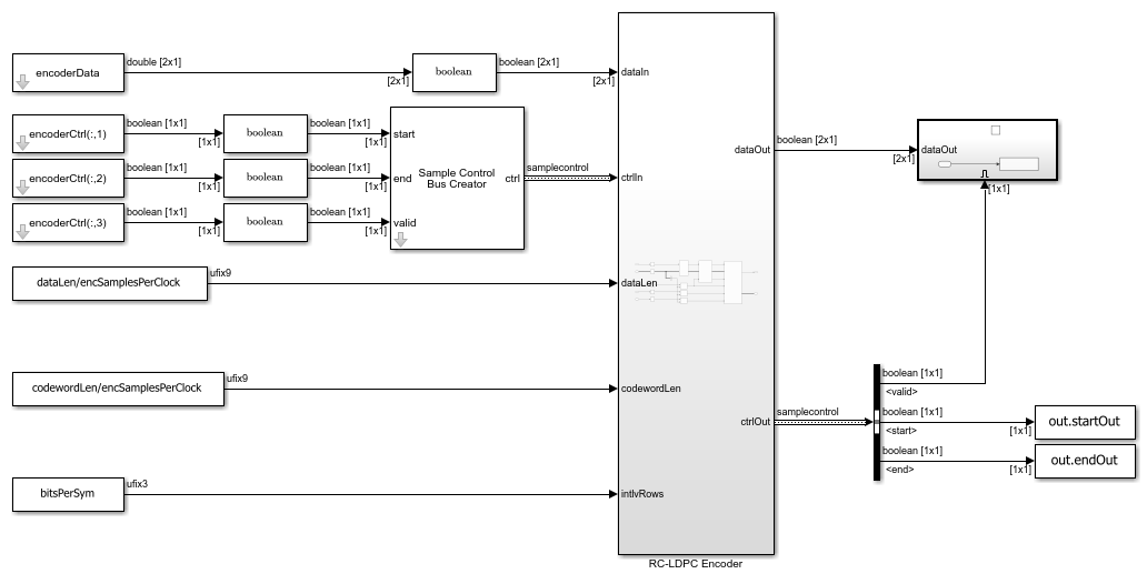
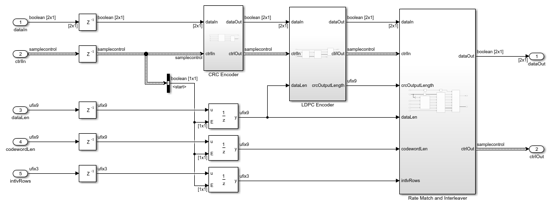
The RC-LDPC encoder subsystem consists of three stages:
The
CRC Encodersubsystem includes the General CRC Generator HDL Optimized block. This block generates and concatenates the CRC bits to the input data bits. This subsystem implements step 1 of the encoder MATLAB reference.The
LDPC Encodersubsystem concatenates filler bits, calculates and concatenates the LDPC parity bits by using the LDPC Encoder block, and then removes the filler bits. This subsystem implements steps 2, 3, and 4 of the encoder MATLAB reference.The
Rate Match and Interleaversubsystem rate-matches the payload buffer to the final output length, and performs block interleaving. Implementing this operation as a single step reduces hardware resources by sharing buffers. This subsystem implements steps 5 and 6 of the encoder MATLAB reference. For details on the vector interleaver architecture, see theBlock Interleaver/Deinterleaver Simulink Architecturesection.
RC-LDPC Decoder MATLAB Reference
The RC-LDPC decoder performs the receive side operations for the coding scheme. The rcldpcDecode function implements the algorithm MATLAB reference. The function decodes the LLRs for one codeword to decode data bits, using the crcCfg and ldpcDecCfg objects to configure the static behavior of the CRC decoder and LDPC decoder, respectively. The LDPC decoder also requires you to specify the number of decoder iterations, decoderIters. Increasing the number of iterations can improve the decoder performance, but increases the latency of the algorithm. Additionally, the data length, dataLen, and number of interleaver rows, intlvRows, define the tunable parameters for the current codeword. These steps describe the implementation of the algorithm.
Deinterleave the input codeword LLRs to create the deinterleaved codeword.
Soft-combine the deinterleaved codeword, if the codeword length is longer than the payload buffer, to create the rate-recovered payload buffer. Soft-combining sums the LLRs that correspond to the same codeword bit to calculate the combined probability from each transmitted repetition. If the codeword size is less than or equal to the payload buffer size, this step has no effect.
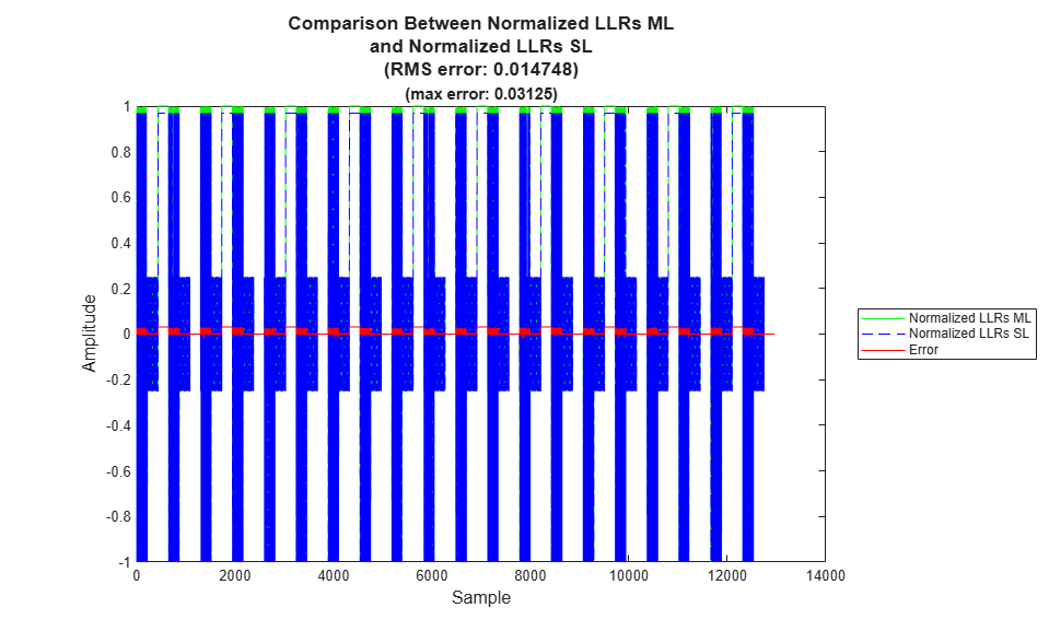
Normalize the receive payload buffer bits to ±1. This step matches the behavior of the Simulink wordlength reduction step, in double precision.
Insert the shortened filler and punctured parity bits to the payload buffer to create the LDPC codeword LLR buffer. Shortened-bit LLRs have a value of 1 because the encoder sets the shortened bits to 0. Punctured LLRs have a value of 0 because punctured bits from the encoder have equal probability to be a 0 or 1.
Decode the LDPC codeword LLRs to generate hard decision LDPC information bits by using the
ldpcDecodefunction.Remove the filler bits from the LDPC information bits, leaving only the data and CRC bits.
Check the received CRC bits by comparing them against recomputed CRC bits from the received data bits by using the
crcDetectfunction. If the received CRC bits do not match the recomputed CRC bits, set thecrcErroutput to 1.Output the received data bits.
This code implements the RC-LDPC decoder. The code is a behavioral reference for the Simulink model.
function [dataOut,crcErr,ldpcDecIn] = rcldpcDecode(dataIn,dataLen,intlvRows,crcCfg,ldpcDecCfg,decoderIters)
%[dataOut,crcErr,ldpcDecIn] = rcldpcDecode(dataIn,dataLen,intlvRows,crcCfg,ldpcDecCfg,decoderIters)
%   Decode RC-LDPC encoded bits.

%   Copyright 2025 The MathWorks, Inc.

    codewordLen = size(dataIn,1);

    crcLen = length(crcCfg.Polynomial)-1;
    ldpcInfoLen = ldpcDecCfg.NumInformationBits;
    ldpcBlockLen = ldpcDecCfg.BlockLength;

    % Validate lengths of output data and input codeword
    assert(dataLen <= (ldpcInfoLen-crcLen),"dataLen (" + num2str(dataLen) + ") must be less than ldpcInfoLen-crcLen (" + num2str(ldpcInfoLen-crcLen) + ")");
    assert(mod(codewordLen,intlvRows) == 0,"codewordLen (" + num2str(codewordLen) + ") must be a multiple of intlvRows (" + num2str(intlvRows) + ")");

    % Bit deinterleaving
    dintlvMat = reshape(dataIn,intlvRows,codewordLen/intlvRows);
    dintlvTran = dintlvMat.';
    dintlvOut = dintlvTran(:);

    Nshort = ldpcInfoLen - crcLen - dataLen;
    Npunc = max(ldpcBlockLen - codewordLen - Nshort,0);

    bufferSize = ldpcBlockLen-Nshort-Npunc;

    % Soft combining
    if codewordLen > bufferSize
        softCombineBuffer = zeros(bufferSize,ceil(codewordLen/bufferSize));
        softCombineBuffer(1:codewordLen) = dintlvOut;
        softCombineOut = sum(softCombineBuffer,2);
    else
        softCombineOut = dintlvOut;
    end

    % Normalize
    normOut = softCombineOut ./ max(abs(softCombineOut));

    % Re-add shortened and punctured bits
    ldpcDecIn = [normOut(1:ldpcInfoLen-Nshort); ones(Nshort,1); normOut(ldpcInfoLen-Nshort+1:end); zeros(Npunc,1)];

    % LDPC Decode
    ldpcDecOut = double(ldpcDecode(ldpcDecIn,ldpcDecCfg,decoderIters));

    % Remove filler bits
    crcDecIn = ldpcDecOut(1:dataLen+crcLen);

    % CRC Decode
    [dataOut,crcErr] = crcDetect(crcDecIn,crcCfg);
end
RC-LDPC Decoder Simulink
The Simulink model implements the RC-LDPC decoder algorithm for HDL code generation. The model uses a fixed-point streaming design with control signals. The design supports multiple samples per clock for the data ports to achieve higher throughput.
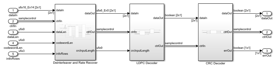
The top level of the model is shown.
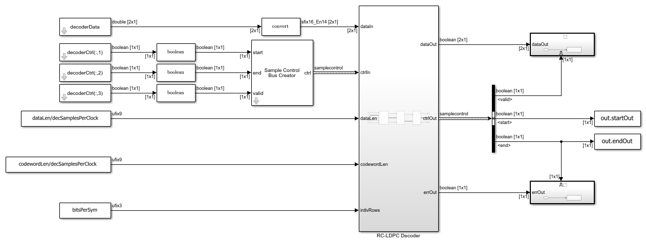
The RC-LDPC Decoder subsystem consists of three stages:
The
Deinterleaver and Rate Recoversubsystem performs block deinterleaving, rate-recovers the received codeword, and inserts shortened and punctured bit probabilities. Implementing this operation as a single step reduces hardware resources by sharing buffers. To optimize the resources of the LDPC decoder implementation, this step also normalizes the LLRs to ±1 and reduces the LLR data type fixed-point word length. This subsystem implements steps 1, 2, 3, and 4 of the decoder MATLAB reference. For details on the vector interleaver architecture, see theBlock Interleaver/Deinterleaver Simulink Architecturesection.The
LDPC Decodersubsystem decodes the LDPC codeword by using the LDPC Decoder block, and then removes the filler bits. This subsystem implements steps 5 and 6 of the decoder MATLAB reference.The
CRC Decodersubsystem uses the General CRC Syndrome Detector HDL Optimized block to check the received CRC bits against the recomputed CRC bits. TheerrOutport indicates a CRC decoding failure. This subsystem implements step 7 of the decoder MATLAB reference.
Block Interleaver/Deinterleaver Simulink Architecture
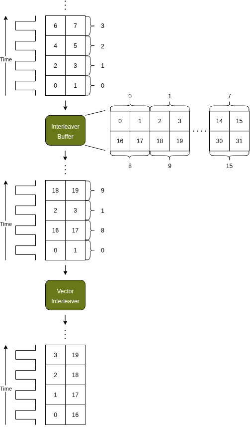
The interleaver Simulink implementation supports multiple samples per clock processing to increase the throughput of the system. The multiple samples per clock architecture has two processing stages: an interleaver buffer that stores codeword data and a vector interleaver that re-orders samples within the vector of SamplesPerClock values. A state machine controls the interleaving steps.
The control state machine writes LDPC codeword bits sequentially into the interleaver buffer. One buffer address corresponds to each vector of SamplesPerClock values. Configuration logic computes the buffer addresses for the start of each row of the interleaver matrix. These addresses create the mapping between physical and virtual interleaver buffer addresses. Each row-start address can correspond to any physical address, depending on the number of shortened, punctured, and repeated bits.
The control state machine reads column-first from the virtual interleaver buffer, and converts virtual addresses to the corresponding physical address using the row-start address mapping.
The vector interleaver reorders the data within each vector to form the final interleaved output. The interleaver takes in the number of interleaver rows samples, and reforms output vectors across rows, and then within each vector.
This figure shows an example of the interleaver behavior, with codeword length of 32, two samples per clock, and two interleaver rows.
In the scalar case, interleaving uses only the interleaver buffer because each read from the buffer corresponds to a single data sample.
The vector deinterleaver implementation uses a mirrored architecture.
The vector deinterleaver reverses interleaving within each vector, to place samplesPerClock samples into each vector.
The control state machine writes column-first into the virtual deinterleaver buffer and converts virtual addresses to the corresponding physical address using the row-start address mapping.
The control state machine reads LDPC codeword LLRs sequentially from the deinterleaver buffer.
Run RC-LDPC Encode and Decode
The example includes two scripts to perform the simulation.
The
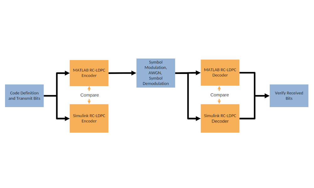
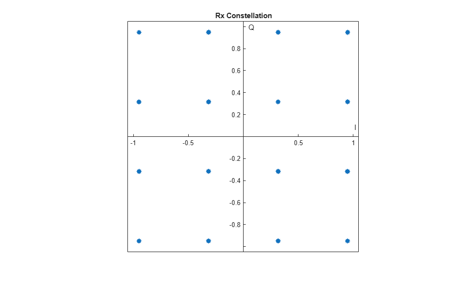
runRCLPDCMLscript defines the coding scheme, tunable codeword parameters, and design constants required by the encoder and decoder. The script runs the encoder MATLAB reference to encode data bits into codewords, distorts the encoded data with a channel model, and then decodes the distorted signal with the decoder MATLAB reference. The channel performs three steps. First, modulate the input codeword bits onto quadrature-amplitude-modulation (QAM) symbols. Second, distort the symbols with additive-white-gaussian noise (AWGN). Last, demodulate the distorted symbols to generate approximate-LLR soft-decisions. The script displays the RC-LDPC code parameters from the coding scheme definition and tunable input parameters. The script verifies the received bits against the transmitted bits, to compute the bit error rate (BER), and uses the CRC error output to compute the block error rate (BLER). The script displays a constellation diagram of the AWGN distorted QAM symbols. Running therunRCLPDCMLscript allows for design exploration in MATLAB.The
runRCLPDCSLscript runs the Simulink simulations for the encoder and decoder, using the coding scheme, tunable codeword parameters, and the design constants fromrunRCLPDCML. The script compares signal tap points in the Simulink model with MATLAB to verify the numerical equivalence of the two implementations. The script displays the latency and throughput results for the encoder and decoder, verifies the received bits against the transmitted bits, counts the CRC errors, and displays the BER and BLER for the Simulink implementation. If you lower the EbN0 value, the BER and BLER from MATLAB and Simulink might differ when bit errors occur. The two implementations are statistically equivalent over a large number of simulated codewords, apart from a small degradation in Simulink BER and BLER due to quantization.
The diagram shows the full simulation setup performed when you run both scripts back to back.
The runRCLPDCML script defines parameters to configure the simulation, the tunable behavior of the RC-LDPC encoder and decoder, and the channel model.
targetCodeRate: Specifies the target code rate for the generated codewords. The target rate is quantized to an integer number of data bits, resulting in an achieved code rate.codewordLen: Specifies the codeword length after rate-matching.bitsPerSym: Specifies the number of codeword bits mapped to a QAM symbol. The bits per symbol also defines the number of interleaver rows for the encoder and decoder.EbN0: Specifies the energy per bit to noise power spectral density in dB for the AWGN channel. Using EbN0 allows for comparable performance results under the AWGN channel between different code rates and modulation schemes.Ncodewords: Specifies the number of codewords to simulate.
This code shows the parameter configuration for the default simulation.
%% Setup Simulation Parameters

% Target code rate of the RC-LDPC codeword, excludes CRC overhead
targetCodeRate = 1/2;

% Number of bits in the codeword
codewordLen = 864;

% Bits per symbol, sets the number of block interleaver columns
bitsPerSym = 4;

% EbN0 for AWGN channel
EbN0 = 50;

% Number of codewords to simulate
Ncodewords = 10;
runRCLDPCML;
RC-LDPC code parameters:
                           Bits
                           ____

    Codeword length:       864
    Information length:    432
    Shortening length:     216
    Puncturing length:     216
    Repetition length:       0

    Target RC-LDPC code rate of 0.5 achieved.

MATLAB bit results:
    Bits transmitted: 4080
    BER: 0%
    BLER: 0%
runRCLDPCSL;
Running rcldpcEncoder.slx
..................

Simulink RC-LDPC Encoder Results:

Simulink RC-LDPC Encoder output matches MATLAB.

Initial Latency: 912s


                             Throughput for 10 codewords @ 1Hz
                             _________________________________

    Codewords per second:               0.00089734
    Data bps:                              0.36612
    Information bps:                       0.38765
    Codeword bps:                          0.77531

Running rcldpcDecoder.slx
....................

Simulink RC-LDPC Decoder Results:

Initial Latency: 3498s


                             Throughput for 10 codewords @ 1Hz
                             _________________________________

    Codewords per second:                0.000274
    Data bps:                             0.11179
    Information bps:                      0.11837
    Codeword bps:                         0.23673

Simulink bit results:
    Bits transmitted: 4080
    BER: 0%
    BLER: 0%
HDL Code Generation and Implementation Results
To generate the HDL code for this example, you must have the HDL Coder™ product. Use the makehdl and makehdltb commands to generate HDL code and an HDL test bench for the rcldpcEncoder/RC-LDPC Encoder and rcldpcDecoder/RC-LDPC Decoder subsystems.
The resulting HDL code was synthesized for a Xilinx® Zynq® UltraScale+ RFSoC ZCU111 evaluation board. The table shows the post place and route resource utilization results. The design meets timing with a clock frequency of 245.76 MHz.
Resource utilization:
       Resource        RC-LDPC Encoder    RC-LDPC Decoder
    _______________    _______________    _______________

    Slice Registers         1664               11342
    Slice LUTs              1450               17160
    RAMB18                     0                   6
    DSP48                      1                   3
Further Exploration
This example supports modifying the coding scheme to create custom implementations tailored to the design requirements. To change the coding scheme, you can edit the Define RC-LDPC Constants section of the runRCLDPCML.m script. The script recalculates the derived RC-LDPC code parameters and checks the settings are valid.
Try changing the CRC polynomial. For example use CRC-8 with polynomial z^8 + z^7 + z^6 + z^4 + z^2 + 1.
crcPoly = [1 1 1 0 1 0 1 0 1];
Try changing the LDPC parity check matrix. For example use rate = 3/4, (N,K) = (1120,840) QC-LDPC mother code.
  qcProto = [5 14 12 1 2 37 45 26 24 0 3 -1 34 7 46 10 -1 -1 -1 -1;
             0 35 1 26 0 10 16 16 34 4 2 23 0 51 -1 49 20 -1 -1 -1;
             12 28 22 46 3 16 51 2 25 29 19 18 52 -1 37 -1 34 39 -1 -1;
             0 51 16 31 13 39 27 33 8 27 53 13 -1 52 33 -1 -1 38 7 -1;
             36 6 3 51 4 19 4 45 48 9 -1 11 22 23 43 -1 -1 -1 14 1];
  blockSize = 56;
This table shows the RC-LDPC code parameters with these changes.
                           Bits
                           ____

    Codeword length:       864
    Information length:    432
    Shortening length:     408
    Puncturing length:       0
    Repetition length:     152
See Also
Blocks
- General CRC Generator HDL Optimized | General CRC Syndrome Detector HDL Optimized | LDPC Encoder | LDPC Decoder