Introduction to Custom OFDM
This example shows the design and verification of a transmitter and receiver for a custom OFDM communication system that is suitable for HDL code generation.
This example uses the resource grid from the Create Custom OFDM Resource Grid example and implements designs for a two-board point-to-point environment. The transmitter and receiver designs both have a MATLAB reference and a Simulink model. The MATLAB reference explores the design space and provides test vectors. The simulink model simulates the fixed-point and latency behavior and generates HDL code.
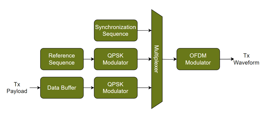
A block diagram of the transmitter design is shown.
A block diagram of the receiver design is shown.

This example is part of a related set of examples for custom OFDM communication systems. For more information see Custom OFDM Reference Applications Overview.
Resource Grid Definition
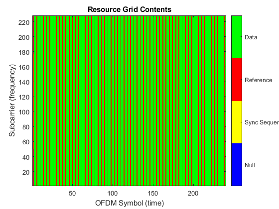
The first stage of designing a custom OFDM communication system is to define the structure and contents of the resource grid. The resource grid is defined as a 2-D matrix in the frequency domain with number of subcarriers (Nsc) rows and number of OFDM symbols (NofdmSyms) columns. OFDM modulation converts this resource grid from the frequency domain to the time domain. The FFT size (Nfft), subcarrier spacing (scs), and the length of the cyclic-prefix (Ncp) determine the symbol bandwidth and duration. The Nfft and Ncp values are in samples, and the scs in kHz. For more information on OFDM see OFDM Modulation Using MATLAB.
The OFDM resource grid is populated by modulated symbols of a specified signal type on each resource element. A resource element is one subcarrier in one OFDM symbol. This allows for the design of custom communication systems where many different signal types are combined to satisfy the system requirements. This example includes the following three signal types. Any resource element without a specified signal type is filled with a null.
Synchronization Sequence - The synchronization sequence is created using a maximal length PN sequence that has good auto-correlation properties. It is placed in the first OFDM symbol of the resource grid to allow the receiver to perform synchronization before data reception.
Reference Symbols - The reference symbols are transmitted interspersed with the data symbols to allow the receiver to estimate and equalize the channel.
Data Symbols - The data symbols carry the information in the resource grid.
This code defines the OFDM resource grid. The example defines the overall grid structure, and then the indices for each signal type in the resource grid. Additionally, the synchronization sequence is generated from a maximal-length PN sequence.
%% Define OFDM Constants

% Define OFDM Resource Grid
Nfft = 256;                  % FFT size in samples
Ncp = 64;                    % Cyclic-prefix length in samples
Nsym = Nfft+Ncp;             % Time domain OFDM symbol length in samples
scs = 30;                    % Subcarrier spacing in kHz
Nsc = 228;                   % Number of active subcarriers in the resource grid
NofdmSyms = 240;             % Number of OFDM symbols in the resource grid
Nguard = (Nfft/2) - (Nsc/2); % Number of guard subcarriers in the resource grid

ofdmSampleRate = scs*1e3*Nfft; % Time domain sample rate in Hz
ofdmFrameDuration = Nsym*NofdmSyms / ofdmSampleRate; % Duration of OFDM frame in seconds

% Define OFDM Grid Signals

% Synchronization Sequence

% Generate constant synchonization sequence from maximum length sequence
syncSeqGen = comm.PNSequence("Polynomial",[7 6 0],"InitialConditions",[1 1 0 1 1 0 1],"SamplesPerFrame",127);
syncSeq = syncSeqGen();

gridOffset = floor((Nsc-length(syncSeq))/2);
ssIdx = (1:length(syncSeq)).'+gridOffset;

% Reference Symbols
refSymSpacing = 4;
refOFDMIdx = 2:refSymSpacing:NofdmSyms;
refSCIdx = repmat((1:Nsc).',length(refOFDMIdx),1);

refIdx =  [refSCIdx reshape(repmat(refOFDMIdx,Nsc,1),[],1)];
refIdx = sub2ind([Nsc,NofdmSyms],refIdx(:,1),refIdx(:,2));

% Data Symbols
dataOFDMIdx = setdiff(2:NofdmSyms,refOFDMIdx);
dataSCIdx = repmat((1:Nsc).',length(dataOFDMIdx),1);

dataIdx =  [dataSCIdx reshape(repmat(dataOFDMIdx,Nsc,1),[],1)];
dataIdx = sub2ind([Nsc,NofdmSyms],dataIdx(:,1),dataIdx(:,2));

dataSymsPerFrame = length(dataOFDMIdx)*Nsc;
bitsPerFrame = dataSymsPerFrame * 2;
OFDM Transmitter MATLAB Reference
The OFDM transmitter performs two operations to generate OFDM frames. Each frame is one repetition of the resource grid. The frames are sent back-to-back to create a continuous transmission.
Resource grid construction - Creates an empty resource grid from the grid structure for each frame. Then, generates contents for each signal type and allocates them to the specified resource element. The synchronization sequence PN-sequence data is BPSK modulated. The reference symbols are generated using a gold sequence and QPSK modulated. The data payload for the frame is indexed from the transmitted bits and QPSK modulated. Symbol modulation uses the
qammodfunction to map bits onto the constellation symbols.OFDM modulation - Converts the resource grid into a time domain waveform to transmit using the
ofdmmodfunction. The resource grid is centered in the FFT by adding guard bands using thenullIndicesparameter. Windowing is performed on the transition between OFDM symbols to suppress the sidelobes of the transmitted waveform.
This code implements the OFDM transmitter. The code is a behavioral reference for the Simulink model.
%% OFDM Transmitter MATLAB

numTxFrames = 1;

% Generate data bits for all transmit frames
txBits = randi([0 1],bitsPerFrame*numTxFrames,1);

txGridML = zeros(Nsc,NofdmSyms*numTxFrames);
for ii = 1:numTxFrames
    % Construct resource grid
    txFrameML = zeros(Nsc,NofdmSyms);

    % Synchronization Sequence - BPSK modulate, add to grid
    syncSyms = qammod(syncSeq,2);
    txFrameML(ssIdx,1) = syncSyms;

    % Reference Symbols - Generate sequence, QPSK modulate, add to grid
    goldSeq = comm.GoldSequence("FirstPolynomial",[31 3 0],"FirstInitialConditions",[zeros(30,1); 1], ...
                            "SecondPolynomial",[31 3 2 1 0],"SecondInitialConditions",arrayfun(@(x) str2double(x),dec2bin(100,31)), ...
                            "Shift",1600,SamplesPerFrame=length(refIdx)*2);
    refBits = goldSeq();
    refSyms = qammod(refBits,4,[2 3 0 1],UnitAveragePower=1,InputType="bit");

    txFrameML(refIdx) = refSyms;

    % Data Symbols - Extract payload for current frame, QPSK modulate, add to grid
    txFramePayload = txBits((ii-1)*bitsPerFrame + (1:bitsPerFrame));
    dataSyms = qammod(txFramePayload,4,[2 3 0 1],UnitAveragePower=1,InputType="bit");

    txFrameML(dataIdx) = dataSyms;

    txGridML(:,(ii-1)*NofdmSyms + (1:NofdmSyms)) = txFrameML;
end

% OFDM Modulate
firstSC = Nguard + 1;
nullIndices = [1:(firstSC-1) (firstSC+Nsc):Nfft].';
ofdmModML = ofdmmod(txGridML,Nfft,Ncp,nullIndices);

% OFDM Symbol Windowing
transmittedSyms = length(ofdmModML)/Nsym;
unwindowed = reshape(ofdmModML,[],transmittedSyms);

windowCoeffs = flipud(0.5*(1-sin(pi*(windowLength+1-2*(1:windowLength).')/(2*windowLength))));
windowedSuffixes = [zeros(windowLength,1), repmat(windowCoeffs, [1 transmittedSyms-1]) .* unwindowed(Ncp + (1:windowLength),1:end-1)];
windowedPrefixes = repmat(flipud(windowCoeffs), [1 transmittedSyms]) .* unwindowed(1:windowLength,:);

txWaveformML = unwindowed;
txWaveformML(1:windowLength,:) = windowedPrefixes + windowedSuffixes;
txWaveformML = txWaveformML(:) * modScalingFactor;

txWaveformMax = max(abs([real(txWaveformML(:)); imag(txWaveformML(:))]));
if any(txWaveformMax >= 0.95)
    warning("Transmitted MATLAB waveform maximum value of " + num2str(txWaveformMax) + " exceeds expected maximum of 0.95, this can cause the fixed point implementation to overflow. Adjust the modScalingFactor.");
end
OFDM Transmitter Simulink
The OFDM transmitter algorithm is implemented in Simulink for HDL code generation. The algorithm is converted into a fixed-point streaming design with control signals. The top level of the model is shown.

The OFDM Transmitter subsystem consists of three stages:
The
Grid Structuresubsystem creates the streaming control signals that construct the resource grid. TheisSyncSeq,isRefandisDataports specify when symbols for the synchronization sequence, reference or data signals are added to the streaming resource grid, respectively. Inside theGrid Structuresubsystem theFrame Counterserializes the resource grid first in the subcarrier dimension, and then along the OFDM symbols and outputs the current subcarrier number and symbol number. TheFrame Counteralso generates the valid signal required to pace the samples through the system. TheframeStartsignal indicates the beginning of each frame. TheFrame Counteris paused when theenableinput port is zero. This signal controls the duty cycle of the transmitted signal. TheFrame Counter Subsystemdrives theResource Element Typesubsystem which implements logic to determine which resource grid element is placed in the resource grid.The
Grid Contentssubsystem creates the symbols for each resource grid element. Each subsystem uses the control signals from theGrid Structureto generate the next symbol for the streaming resource grid. The subsystems are delay balanced and the signal types are multiplexed together to form the input to the OFDM modulator. For the synchronization sequence, a counter increments through a lookup table containing the bit sequence and a BPSK modulator converts the bits to symbols. For the reference symbols, a gold sequence generator block creates the bit sequence and a QPSK modulator converts the bits to symbols. For the data, a FIFO stores the transmit payload bits. This FIFO is loaded from outside the transmitter using a streaming interface with backpressure provided by the ready signal. The interface expects two bits per clock as a vector, this provides enough data to the QPSK modulator to meet throughput. The ready signal goes low when a full frame of data bits is stored. At the beginning of each frame if the ready signal is high then no data will be transmitted for the entire frame, and nulls will be inserted on the data resource elements. When the subsequent frame starts, if the ready is now low, data will be transmitted. By providing enough data to the input, continuous data transmission can be achieved.The
OFDM Modulatorblock creates the time-domain transmitter waveform. It is parameterized by the resource grid definition and performs all stages of OFDM modulation and inter-symbol windowing. The OFDM modulator fixed-point wordlength grows by log2 ofNfftbetween the input and the output. The output from the OFDM modulator is multiplied by a scaling factor and the reciprocal of the FFT size in theOFDM Mod Scalingsubsystem. The scaling factor is empirically selected through simulation so the final output is approximately within the range +/-0.8. this is a trade-off between using the full dynamic range of the fixed-point data types while leaving overhead for downstream processing when integrated into a target device.

When converting from frame-based MATLAB code to a streaming Simulink model, the pacing of data with control signals must be considered. This example uses a single Simulink rate to implement the whole algorithm - this rate represents the clock in the generated HDL code. The output from the transmitter will feed the digital-to-analog converter (DAC) when deployed on the target board, and the same clock may drive both components. Therefore, the transmitter must be capable of producing a valid output sample every clock cycle, after an initial latency. This constraint defines the valid behavior through the model.
The output txValid signal from the transmitter is the output from the OFDM modulator. The OFDM modulator block is designed to meet this requirement with a constant valid output, if the input data is correctly paced. OFDM modulation increases the length of the output relative to the input by adding guard subcarriers and the cyclic-prefix to the signal. For an input length of Nsc, the output length is Nsc + Ncp + Nguard * 2. In a streaming design this means the output takes more cycles than the input. Therefore, a gap of Ncp + Nguard * 2 must be left between each input to allow for the OFDM modulator to finish outputting the previous OFDM symbol. If the input data stalls, the output valid will fall and the DAC will not receive data. Conversely, if the input data is provided too fast then the OFDM modulator will drop the data. Both of these outcomes result in data loss from the transmitter. The data pacing is handled by the Frame Counter valid output, the valid is high for Nsc cycles and then goes low for Nsym - Nsc cycles. This duty cycle ensures that the output from the transmitter will stay high. A timing diagram of the input and output from the OFDM modulator, with the corresponding valid signals, is shown.

OFDM Receiver MATLAB Reference
The OFDM receiver performs four operations. Firstly, the receiver synchronizes the received waveform. Secondly, the synchronized waveform is OFDM demodulated to recover the resource grid. Thirdly, the grid reference symbols are used to estimate the channel and equalize the grid data symbols. Finally, the equalized symbols are symbol demodulated to recover the received bits.
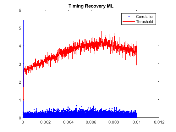
Synchronization is performed to measure and correct for timing and frequency offsets. Timing offset estimation is achieved by correlation between the received time domain signal and the expected synchronization sequence. A timing correlation threshold is also computed by measuring the power of the signal over the same period as the correlation. This reduces the probability of false detections when the signal power is high. Additionally, a minimum threshold is applied to prevent false detections if the signal power is too low. Frequency offset estimation is achieved by the cyclic-prefix correlation method over one OFDM symbol. When the timing correlation crosses its threshold value a peak finder searches for the local maximum across a window of
peakWindowLengthsamples to acquire the optimal timing point. The frequency offset measurement at the peak sample is used for the frequency correction. Therefore, the frequency estimation is the result of cyclic-prefix correlation across the symbol containing the synchronization sequence. In addition to the initial timing synchronization, sample slip tracking is performed after the initial synchronization and updates the timing offset each frame. This tracking allows for continuous reception under the effects of sample clock misalignment between the transmitter and the receiver. Frequency offset correction is applied to the time aligned received waveform before OFDM demodulation and is updated once per frame with the estimate from the latest synchronization sequence OFDM symbol. ThefreqCorrectionEnvariable enables the frequency offset correction, it is disabled by default to simplify comparison between the MATLAB reference and the Simulink implementation.OFDM demodulation uses the
ofdmdemodfunction to convert the time and frequency corrected waveform to the received resource grid. A cyclic-prefix fraction of 0.5 is used to shift the FFT window so that is starts half way through the cyclic-prefix. This avoids the windowed edges of the OFDM symbols, and reduces inter-symbol interference with the non-ideal timing offset recovery.To estimate the channel the reference symbols are extracted from the received grid using frame structure definition. The expected reference symbols are recreated and a least-squares estimate is performed between the received reference symbols and the expected reference symbol. This estimates the channel at the location of each reference symbol. The channel estimates at these points are then interpolated to estimate the channel for all resource elements that contain data symbols. The reference symbol structure in this example fills one entire OFDM symbol, therefore no interpolation is required in frequency. Linear interpolation between the OFDM symbols containing reference symbols is performed between each pair of neighboring columns. The resource grid contains data symbols after the last column of reference symbols in the resource grid. For these OFDM symbols the channel estimate from the last reference symbol is repeated. The channel estimate is then applied to the received data symbols to perform phase-equalization. Magnitude equalization is not performed as the data symbols are QPSK.
Symbol demodulation uses the
qamdemodfunction to perform hard-decision demodulation and recover the bits from the equalized resource grid.
This code implements the OFDM receiver. The code is a behavioral reference for the Simulink model.
%% OFDM Receiver MATLAB

% Control applying frequency offset correction
freqCorrectionEn = 0;

% Input Scaling
scaledWaveform = 0.875 * rxWaveform;

% Timing Synchronization

% Correlation
ssCorrML = abs(filter(corrWeightsQ,1,scaledWaveform)).^2;

% Threshold
energyFilt = ones(Nfft,1);
energy = filter(energyFilt,1,abs(scaledWaveform).^2);
thresholdML = corrThreshold * energy;
thresholdML(thresholdML<hardThreshold) = hardThreshold;

% Determine where the threshold is exceeded
thresholdExceededML = ssCorrML(ssCorrML > thresholdML);
exceeds   = ssCorrML > thresholdML;
survivors = ssCorrML .* exceeds;
exceedingIndices = find(exceeds);

if isempty(exceedingIndices)
    error("No Synchrnonization sequence detected.")
end

% Frequency Synchronization
sDelayed  = [zeros(Nfft,1); scaledWaveform(1:end-Nfft)];
cpProduct = scaledWaveform .* conj(sDelayed);
cpXCorr = filter(ones(Ncp,1),1,cpProduct);

frameStartIndex = [];
peakInfoML = [];

triggerIndex = exceedingIndices(1);

while (triggerIndex + peakWindowLength -1) <= length(survivors)
    [~,peakSubIndex] = max(survivors(triggerIndex:triggerIndex++peakWindowLength-1));
    index = triggerIndex + peakSubIndex - 1;

    if exceeds(index)
        peak.Correlation = ssCorrML(index);
        peak.Energy      = energy(index);
        startIndex = index - (Nsym - 1);
        if startIndex <= 0
      	    error("Timing offset is before the start of the received waveform.");
        end
        frameStartIndex = [frameStartIndex startIndex]; %#ok<AGROW>
        peak.tOffset = mod(startIndex-1,Nsym*NofdmSyms);
        peak.fOffset = round(scs * 1e3 * angle(cpXCorr(index)) / (2*pi));

        peakInfoML  = [peakInfoML peak]; %#ok<AGROW>

    end

    % Move the resume index to the start of the next window
    triggerIndex = index + NofdmSyms * Nsym - floor(peakWindowLength/2);
end

samplesBetweenSync = diff(frameStartIndex);

% Apply frequency offset with tracking
if freqCorrectionEn
    fOffset = complex(zeros(size(scaledWaveform)));

    prevPhaseAccum = 0;
    for ii = 1:length(peakInfoML)
        sIdx = frameStartIndex(ii);
        if ii == length(peakInfoML)
            eIdx = length(fOffset);
        else
            eIdx = min(sIdx+samplesBetweenSync(ii)-1,length(fOffset));
        end

        t = ((0:eIdx-sIdx) + (ii~=1)).'/ofdmSampleRate;

        phaseAccum = peakInfoML(ii).fOffset.*t + prevPhaseAccum;
        fOffset(sIdx:eIdx) = exp(-1i*2*pi*(phaseAccum));

        prevPhaseAccum = phaseAccum(end);
    end

    frequencyCorrected = scaledWaveform .* fOffset;
else
    frequencyCorrected = scaledWaveform;
end

% OFDM Demodulate
maxNumOFDMSymsRec = floor((length(scaledWaveform)) / Nsym);
numOFDMSymsRec = 0;

firstSC = Nguard + 1;
nullIndices = [1:(firstSC-1) (firstSC+Nsc):Nfft].';

rxGridML = zeros(Nsc,maxNumOFDMSymsRec);
for ii = 1:length(peakInfoML)
    % Calculate the start and end index for this demodulation
    % One demodulation is performed per synchronization sequence detection to allow
    % for timing adjustments to be applied.
    sIdx = frameStartIndex(ii);

    % Maximum end index is the end of the waveform
    maxEIdx = floor((length(scaledWaveform) - sIdx + 1) / Nsym) * Nsym + sIdx - 1;

    if ii == length(peakInfoML)
        % Last detection so demodulate until the end
        eIdx = maxEIdx;
    else
        % Demodulate until the next detection
        eIdx = min(round(samplesBetweenSync(ii) / (Nsym * NofdmSyms)) * (Nsym * NofdmSyms) + sIdx - 1,maxEIdx);
    end

    ofdmDemodInML = frequencyCorrected(sIdx:eIdx);
    rxFrameML = ofdmdemod(ofdmDemodInML,Nfft,Ncp,Ncp*0.5,nullIndices);
    rxGridML(:,numOFDMSymsRec + (1:size(rxFrameML,2))) = rxFrameML;
    numOFDMSymsRec = numOFDMSymsRec + size(rxFrameML,2);
end

rxGridML = rxGridML(:,1:numOFDMSymsRec) / demodScalingFactor;

rxWaveformMax = max(abs([real(rxGridML(:)); imag(rxGridML(:))]));
if any(rxWaveformMax >= 0.95)
    warning("Received MATLAB grid maximum value of " + num2str(rxWaveformMax) + " exceeds expected maximum of 0.95, this can cause the fixed point implementation to overflow. Adjust the demodScalingFactor.");
end

numOFDMSymsRec = size(rxGridML,2);
numRxFrames = floor(numOFDMSymsRec / NofdmSyms);

if numRxFrames < 1
    warning("rxWaveform does not contain an entire OFDM frame to demodulate.")
end

rxDataSymsEqML_diag = zeros(dataSymsPerFrame*numRxFrames,1);
rxBitsML = zeros(bitsPerFrame*numRxFrames,1);

for ii = 1:numRxFrames
    rxFrameML = rxGridML(:,(ii-1)*NofdmSyms + (1:NofdmSyms));

    % Channel Estimate
    rxRefSymsML = rxFrameML(refIdx);

    % Channel Estimate Generate Reference Symbols
    goldSeq = comm.GoldSequence("FirstPolynomial",[31 3 0],"FirstInitialConditions",[zeros(30,1); 1], ...
                            "SecondPolynomial",[31 3 2 1 0],"SecondInitialConditions",arrayfun(@(x) str2double(x),dec2bin(100,31)), ...
                            "Shift",1600,SamplesPerFrame=length(refIdx)*2);
    refBits = goldSeq();
    refSyms = qammod(refBits,4,[2 3 0 1],UnitAveragePower=1,InputType="bit");

    % Channel Estimate Least Squares
    hpML = rxRefSymsML(:)./refSyms(:);
    hpGridML = reshape(hpML,Nsc,[]);

    % Channel Estimate Time Interpolation
    hEstML = zeros(Nsc,length(dataOFDMIdx));
    hEstPos = 0;
    for jj = 1:size(hpGridML,2)
        if jj ~= size(hpGridML,2)
            prevEst = hpGridML(:,jj);
            curEst = hpGridML(:,jj+1);

            estGap = refOFDMIdx(jj+1) - refOFDMIdx(jj);
            estDelta = (curEst-prevEst) / estGap;

            hEstML(:,hEstPos+(1:estGap-1)) = prevEst + estDelta * (1:estGap-1);

            hEstPos = hEstPos+estGap-1;
        else
            if jj == 1 % Only one reference OFDM symbol
                curEst = hpGridML;
            end
            hEstML(:,hEstPos + (1:NofdmReplSyms)) = repmat(curEst,1,NofdmReplSyms);
        end
    end

    % Channel Equalize
    rxDataSymsML = rxFrameML(dataIdx);
    rxDataSymsEqML = rxDataSymsML .* conj(hEstML(:));

    % Store all the received symbols for diagnostics
    rxDataSymsEqML_diag((ii-1)*dataSymsPerFrame + (1:dataSymsPerFrame)) = rxDataSymsEqML;

    % QPSK Demod
    rxFramePayload = qamdemod(rxDataSymsEqML,4,[2 3 0 1],UnitAveragePower=1,OutputType="bit");
    rxBitsML((ii-1)*bitsPerFrame + (1:bitsPerFrame)) = rxFramePayload;
end
OFDM Receiver Simulink
The OFDM receiver algorithm is implemented in Simulink for HDL code generation. The algorithm is converted into a fixed-point streaming design with control signals. The top level of the model is shown.
The OFDM Receiver subsystem consists of five stages:
The
Input Scalingsubsystem scales the input signal by 0.875. This provides a small overhead in the fixed-point scaling for downstream operations, avoiding overflow, without growing the wordlength. The scaled signal is rounded to prevent the introduction of DC error, which can heavily distort an OFDM signal.The
Synchronizationsubsystem performs the time and frequency synchronization algorithms. The time and frequency estimations are computed in parallel on the input data stream. The timing offset correlation is performed using an FIR filter. The frequency offset estimator performs the cyclic-prefix correlation and converts the result to a phase angle using CORDIC. TheTiming OffsetandFrequency Offsetsubsystems have different latencies. Their output signals and the received data must be realigned to allow the corrections to be applied. This is implemented using two stream synchronizer subsystems that use the valid signals and FIFOs to align the data and frequency estimation streams with the slower timing offset stream. TheFrequency Correctionsubsystem corrects the frequency offset using an NCO. ThestrobeandtDeltaoutput signals indicate the start of an OFDM frame, and the timing offset difference relative to the previous frame respectively. For the initial synchronizationtDeltais zero. TheSynchronizationsubsystem provides diagnostic information for the correlation, threshold, timing offset and frequency offset of each peak on thepeakInfoport.The
OFDM Demodulationsubsystem uses theOFDM Demodulatorblock to recover the OFDM resource grid from the time and frequency synchronized signal. A state machine applies the timing delta at the start of each frame. If the timing delta is positive (i.e. the timing is delayed from the previous frame) the input valid to the OFDM demodulator goes low to delay the demodulation of the next frame. If the timing delta is positive (i.e. the timing is advanced from the previous frame) then the cyclic-prefix length is shortened to advance the demodulation of the next frame. The OFDM demodulator grows the output wordlength by log2 ofNfft. However, this full dynamic range is only required when the signal energy is concentrated in a small number of subcarriers. In practice, the system performance can be preserved by applying a scaling factor and reducing the wordlength by square route of the FFT size. The scaling factor is empirically selected through simulation so the final output is approximately within the range +/-0.8.The
Channel Estimation and Equalizationsubsystem uses a least-squares channel estimator and phase-equalizer to equalize the received data symbols. The resource grid is streamed into the subsystem and theGrid Structuresubsystem performs the indexing operations to extract the data and reference streams. The reference streams are used by theChannel Estimationsubsystem to approximate the channel. The output from theChannel Estimationsubsystem is the channel estimate for each data symbol. The channel is not estimated in locations that do not contain data to be equalized. The estimated channel stream is then aligned with the data symbols and is used for equalization. The stream alignment is performed with a stream synchronizer that waits for data to be ready from both streams before outputting the aligned data. The fixed-point data types for the channel estimator are designed for the output from the OFDM demodulation scaling factor. With this constraint the output channel estimates are the same data type as the input. For the channel equalization the multiplication grows a single integer bit, and maintains the same wordlength by discarding a single fractional bit, to prevent overflow.The
QPSK Demodulationsubsystem converts the equalized received data symbols into hard decision bits by slicing the complex signal into real and imaginary parts and comparing to zero. The output stream is a vector of two bits per clock.
Run OFDM Transmit and Receive
The example includes two scripts to perform the simulation.
The
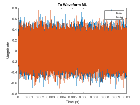
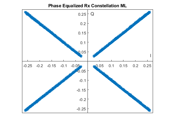
runIntroOFDMMLscript defines the OFDM resource grid structure, contents, and the design constants required by the transmitter and receiver. The script runs the transmitter MATLAB reference, distorts the transmit waveform with a wireless channel model, and then receives the distorted signal with the receiver MATLAB reference. By default, the wireless channel is implemented as a rician fading channel. Additionally, AWGN, frequency offset, and sample rate offset impairments can be optionally included. The received bits are verified against the transmitted bits and additional diagnostics are plotted to verify the overall system performance. TherunIntroOFDMMLscript simulation allows for design exploration in MATLAB.The
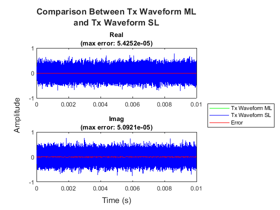
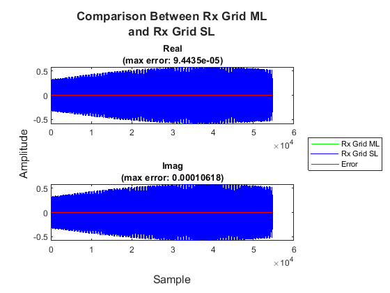
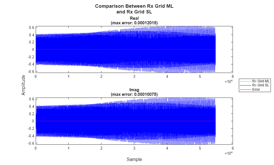
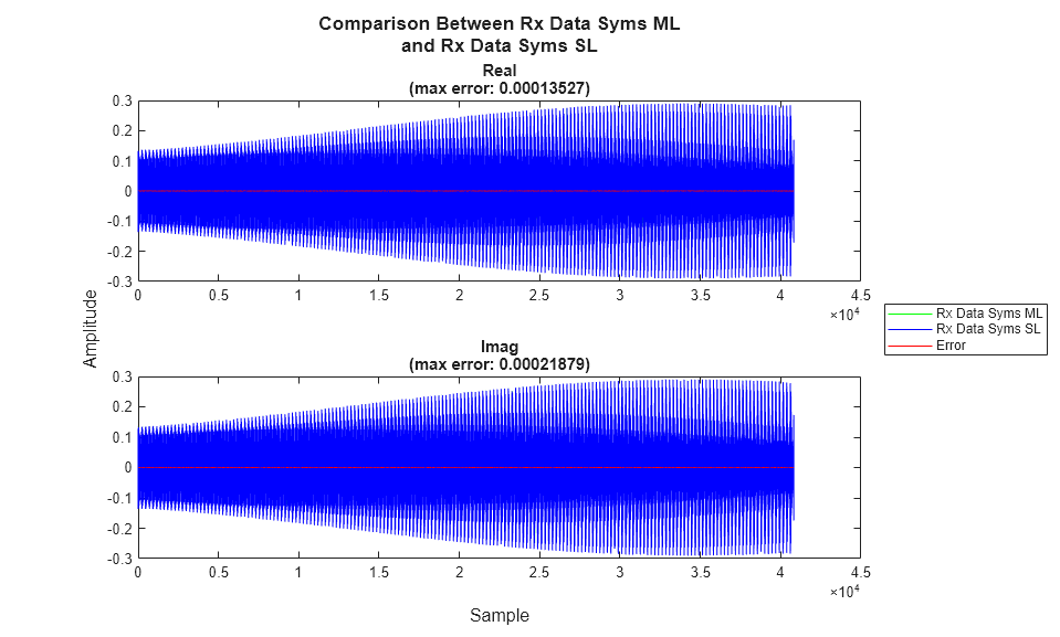
runIntroOFDMSLscript runs the Simulink simulations for the transmitter and receiver, using the resource grid structure, contents, and the design constants fromrunIntroOFDMML. Signal tap points in the Simulink model are compared with MATLAB to verify the numerical equivalence of the two implementations. The received bits are verified against the transmitted bits.
The diagram shows the full simulation setup performed when both scripts are run back to back.

runIntroOFDMML;
MATLAB received bits match transmitted bits.

Synchronization Results ML:

    Correlation    Energy    tOffset    fOffset
    ___________    ______    _______    _______

      5.0128       6.0799      19         42

runIntroOFDMSL;
Running introOFDMTransmitter.slx
....................
Running introOFDMReceiver.slx
....................
Simulink received bits match transmitted bits.

Synchronization Results SL:

    Correlation    Energy    tOffset    fOffset
    ___________    ______    _______    _______

      5.0127       6.0801      19        41.86

HDL Code Generation and Implementation Results
To generate the HDL code for this example, you must have the HDL Coder™ product. Use the makehdl and makehdltb commands to generate HDL code and an HDL test bench for the introOFDMTransmitter/OFDM Transmitter and introOFDMReceiver/OFDM Receiver subsystems.
The OFDM Receiver HDL code was generated with an oversample factor of 32 to share DSP resources within the synchronization sequence correlator. The oversample factor is calculated as the target clock rate (245.76e6) / algorithm sample rate (7.68e6).
The resulting HDL code was synthesized for a Xilinx® Zynq® UltraScale+ RFSoC ZCU111 evaluation board. The table shows the post place and route resource utilization results. The design meets timing with a clock frequency of 245.76 MHz.
Resource utilization:
       Resource        OFDM Transmitter    OFDM Receiver
    _______________    ________________    _____________

    Slice Registers          9221              15082
    Slice LUTs               4418               9671
    RAMB18                      4                 10
    RAMB36                     12                  1
    DSP48                      18                 65