visionhdl.MeasureTiming
Measure timing of pixel control structure input
Description
The visionhdl.MeasureTiming
System object™ measures the timing parameters of a video stream. The Vision HDL Toolbox™ streaming pixel protocol implements the timing of a video system,
including inactive intervals between frames. These inactive intervals are called
blanking intervals. Many Vision HDL Toolbox objects require minimum blanking intervals. You can use the timing
parameter measurements from this object to check that your video stream meets these
requirements. If you manipulate the control signals of your video stream, you can use
this object to verify the resulting control signals. To determine the parameters of each
frame, the object measures time steps between the control signals in the input
structure.
For details on the pixel control bus and the dimensions of a video frame, see Streaming Pixel Interface. For more information on blanking intervals, see Configure Blanking Intervals.
To measure the timing of the pixel control structure input:
Create the
visionhdl.MeasureTimingobject and set its properties.Call the object with arguments, as if it were a function.
To learn more about how System objects work, see What Are System Objects?
Creation
Description
MT = visionhdl.MeasureTiming
Usage
Description
[
incorporates the current pixel location into calculations of video frame timing.
The control signals, activePixels,activeLines,totalPixels,totalLines,horizBlank,vertBlank]
= MT(ctrlin)ctrlin, associated with each pixel
indicate the location of this pixel relative to the active frame boundaries. The
input object measures the time steps between the control signals to determine
the parameters of each frame.
For details about the pixel stream format, see Streaming Pixel Interface.
Input Arguments
Output Arguments
The diagram shows the output measurements, as determined from the pixel stream control signals.
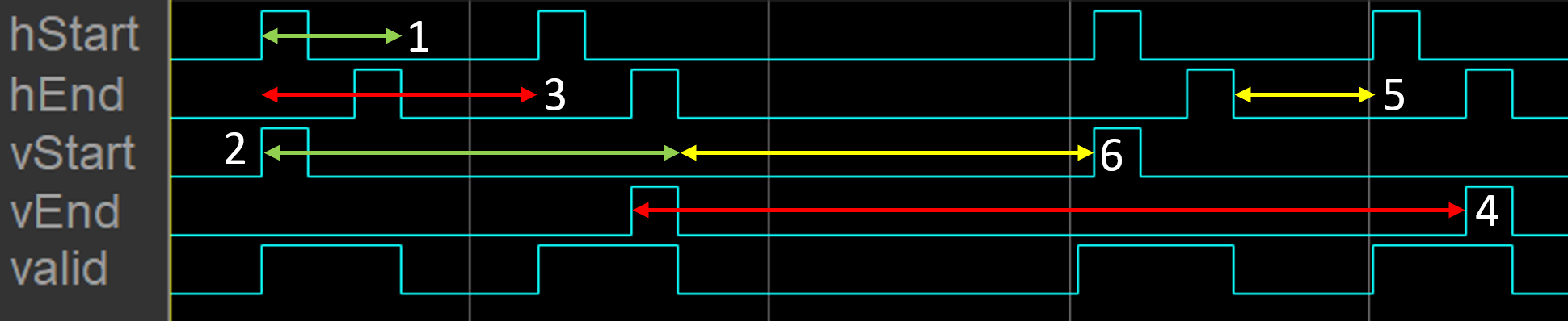
1— Active pixels per line2— Active lines per frame (counthStartpulses)3— Total pixels per line4— Total lines per frame (cycles divided by total pixels per line)5— Horizontal blanking6— Vertical blanking (cycles, minus horizontal blanking, divided by total pixels per line)
For details on the pixel control bus and the dimensions of a video frame, see Streaming Pixel Interface.
Note
Measurements from the first simulated frame are incorrect because some parameters require measurements between frames. Before using the results, simulate at least two frames.
This value is measured between hStart and
hEnd. See marker 1 in the
diagram.
Data Types: double
This value is measured as the number of hStart
pulses between vStart and vEnd.
See marker 2 in the diagram.
Data Types: double
This value is measured from hStart to the next
hStart, including the horizontal blanking
interval. See marker 3 in the diagram.
Data Types: double
This value is measured by the interval from vEnd to
the next vEnd, divided by
totalPixels. It includes the vertical blanking
interval. See marker 4 in the diagram.
Data Types: double
The horizontal blanking interval is the number of inactive pixels
between lines of a frame. This value is measured between
hEnd and the next hStart. See
marker 5 in the diagram.
Data Types: double
The vertical blanking interval is the number of inactive lines between
frames. This value is measured from vEnd to the next
vStart, adjusted to remove
horizBlank, then divided by
totalPixels. See marker 6 in
the diagram.
Data Types: double
Object Functions
To use an object function, specify the
System object as the first input argument. For
example, to release system resources of a System object named obj, use
this syntax:
release(obj)
Examples
This example shows how to use the MeasureTiming object to observe the frame parameters in a custom video stream. The example creates customized padding around an image frame and converts the frame to streaming video. It uses the MeasureTiming object to confirm that the streaming video parameters match the custom settings.
Use a FrameToPixels object to specify a small custom-size frame with customized blanking intervals. To obtain a frame of this size, select a small section of the input image.
frm2pix = visionhdl.FrameToPixels( ...
      'VideoFormat','custom', ...
      'ActivePixelsPerLine',32, ...
      'ActiveVideoLines',18, ...
      'TotalPixelsPerLine',42, ...
      'TotalVideoLines',26, ...
      'StartingActiveLine',6, ...
      'FrontPorch',5);
[actPixPerLine,actLine,numPixPerFrm] = getparamfromfrm2pix(frm2pix);

frmFull = imread('rice.png');
frmIn = frmFull(74:73+actLine,104:103+actPixPerLine);
imshow(frmIn)

Create a MeasureTiming object to observe the parameters of the serial pixel output from the FrameToPixels object.
measure = visionhdl.MeasureTiming;
Serialize the input frame.
[pixInVec,ctrlInVec] = frm2pix(frmIn);
Some parameters require measurements between frames, so you must simulate at least two frames before using the results. Because you serialized only one input frame, process that frame twice to measure all parameters correctly.
for f = 1:2
      for p = 1:numPixPerFrm
          [activePixels,activeLines,totalPixels,totalLines, ...
              horizBlank,vertBlank] = measure(ctrlInVec(p));
      end
      fprintf('\nFrame %d:\n',f)
      fprintf('activePixels: %f\n',activePixels)
      fprintf('activeLines: %f\n',activeLines)
      fprintf('totalPixels: %f\n',totalPixels)
      fprintf('totalLines: %f\n',totalLines)
      fprintf('horizBlank: %f\n',horizBlank)
      fprintf('vertBlank: %f\n',vertBlank)
end
Frame 1:
activePixels: 32.000000
activeLines: 18.000000
totalPixels: 42.000000
totalLines: 22.880952
horizBlank: 10.000000
vertBlank: 4.880952
Frame 2:
activePixels: 32.000000
activeLines: 18.000000
totalPixels: 42.000000
totalLines: 26.000000
horizBlank: 10.000000
vertBlank: 8.000000
The measurements after the first frame are not accurate. However, after the second frame, the measurements match the parameters chosen in the FrameToPixels object.
Version History
Introduced in R2016b