Active Differential
Spur or planetary active differential gear
Libraries:
Vehicle Dynamics Blockset /
Powertrain /
Drivetrain /
Final Drive Unit
Description
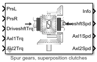
The Active Differential block implements an active differential to account for the power transfer from the transmission to the axles. The block models the active differential as an open differential coupled to either a spur or planetary differential gear set. The block uses external pressure signals to regulate the clutch pressure to either speed up or slow down each axle rotation.
Use the block in hardware-in-the-loop (HIL) and optimization workflows to dynamically couple the driveshaft to the wheel axles when you want to direct the transmission torque to a specific axle. For detailed front wheel driving studies, use the block to couple the driveshaft to universal joints. The block is suitable to use in system-level closed-loop control studies, for example, yaw stability and torque vectoring. All the parameters are tunable.
To specify the active differential, open the Active Differential parameters and specify Active differential type.
Setting | Block Implementation |
|---|---|
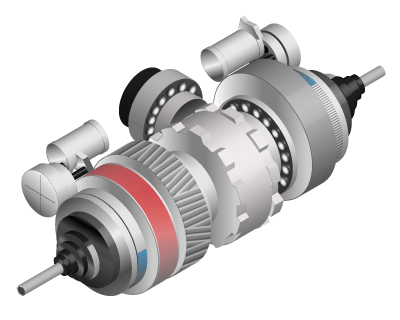
Spur gears, superposition clutches | Clutches are in superposition through a three-gang gear system and a differential case |
Double planetary gears, stationary clutches | Clutches are fixed to the carrier and axles through double planetary gear sets |
Use the Open Differential parameter Crown wheel (ring gear) located to specify the open differential location, either to the left or right of the center-line.
Depending on the available data, to specify the method to couple the different torques applied to the axles, use the Slip Coupling parameter Coupling type.
Setting | Block Implementation |
|---|---|
Pre-loaded ideal clutch | Torque modeled as a dry clutch with constant friction coefficients |
Slip speed dependent torque
data | Torque determined from a lookup table that is a function of slip-speed and clutch pressure |
The Active Differential block does not include a controller or external clutch actuator dynamics. Use this information to control the input clutch pressure. The info bus contains the slip speeds at clutch 1, Δωcl1, and clutch 2, Δωcl2.
Input Axle Torque | Δωcl1 | Δωcl2 | Input Clutch Pressure |
|---|---|---|---|
Positive axle 1 torque |
| N/A | Increase clutch 1 pressure |
Positive axle 1 torque |
| N/A | Disengage clutch 1 and 2 |
Positive axle 2 torque | N/A |
| Increase clutch 1 pressure |
Positive axle 2 torque | N/A |
| Disengage clutch 1 and 2 |
Differentials
The Active Differential block implements these equations to represent the mechanical dynamic response for the superposition and stationary clutch configurations. To determine the gear ratios, the block uses the clutch speed and the number of teeth for each gear pair. The allowable wheel speed difference (AWSD) limits the wheel speed difference for positive torque.
Mechanical Dynamic Response | Equations | |
|---|---|---|
Superposition Clutches and Spur Gearing | Stationary Clutches and Planetary Gearing | |
Crown gear |
|
|
Axle 1 |
|
|
Axle 2 |
|
|
Gear ratios |
|
|
Rigid Coupling Constraints |
|
|
Allowable wheel speed difference (AWSD) |
|
|
These superposition clutch illustrations show the clutch configuration and schematic for torque transfer to the left wheel.
The illustrations show the stationary clutch configuration and schematic.
Slip Coupling
For both the ideal clutch and slip-speed configurations, the slip coupling is a function of the slip-speed and clutch pressure. The slip-speed depends on the slip velocity at each of the clutch interfaces.
The ideal clutch coupling model uses the axle slip speed, clutch pressure, and friction to calculate the clutch torque. The friction coefficient is a function of the slip speed.
To calculate the total clutch force, the block uses the effective radius, clutch pressure, and clutch preload force.
The disc radii determine the effective clutch radius over which the clutch force acts.
To calculate the clutch torque, the slip speed coupling model uses torque data that is a function of slip speed and clutch pressure. The angular velocities of the axles determine the slip speed.
The equations use these variables.
| Aeff | Effective clutch pressure area |
| bd | Crown gear linear viscous damping |
| b1, b2 | Axle 1 and 2 linear viscous damping, respectively |
| Fc, FT | Clutch preload force and total force, respectively |
| Jd | Carrier rotational inertia |
| Jgc | Three-gang gear rotational inertia |
| Jc1, Jc2 | Planetary carrier 1 and 2 rotational inertia, respectively |
| Jr1, Jr2 | Planetary ring gear 1 and 2 rotational inertia, respectively |
| Js1, Js2 | Planetary sun gear 1 and 2 rotational inertia, respectively |
| J1, J2 | Axle 1 and 2 rotational inertia, respectively |
| N | Carrier-to-drive shaft gear ratio |
| Nd | Number of disks |
| Ns1, Ns2 | Clutch 1 and 2 carrier-to-spur gear ratio, respectively |
| Np1, Np2 | Planetary 1 and 2 carrier-to-axle gear ratio, respectively |
| P1, P2 | Clutch 1 and 2 pressure, respectively |
| Reff | Effective clutch radius |
| Ri, Ro | Annular disk inner and outer radius, respectively |
| Tc | Clutch torque |
| Tcl1, Tcl2 | Clutch 1 and 2 coupling torque, respectively |
| Td | Driveshaft torque |
| T1, T2 | Axle 1 and 2 torque, respectively |
| Ti | Axle internal resistance torque |
| Ti1, Ti2 | Axle 1 and 2 internal resistance torque |
| ωd | Driveshaft angular velocity |
| ϖ | Slip speed |
| ω1, ω2 | Axle 1 and 2 angular velocity, respectively |
Δωcl1, Δωcl2 | Clutch 1 and 2 slip speed at interface, respectively |
ωcl1, ωcl2 | Clutch 1 and 2 angular velocity, respectively |
| μ | Clutch coefficient of friction |
| zi | Number of teeth on gear i |
Examples

Double Lane Change Reference Application
Simulate a full vehicle dynamics model undergoing a double lane change maneuver standard ISO 3888-2. Use for vehicle dynamics ride and handling analysis and chassis controls development, including yaw stability and lateral acceleration limits.
Ports
Inputs
Output
Parameters
References
[1] Deur, J., Ivanović, V., Hancock, M., and Assadian, F. "Modeling of Active Differential Dynamics." In ASME proceedings. Transportation Systems. Vol. 17, pp: 427-436.
Extended Capabilities
Version History
Introduced in R2018b