Coordinate Systems for Unreal Engine Simulation in UAV Toolbox
UAV Toolbox enables you to simulate your UAV scenario in a virtual environment that uses the Unreal Engine® from Epic Games®.
Note
Simulating models in the 3D visualization environment requires Simulink® 3D Animation™.
UAV Toolbox uses these coordinate systems to position objects in the Unreal Engine visualization environment.
Unreal Engine World Coordinate System
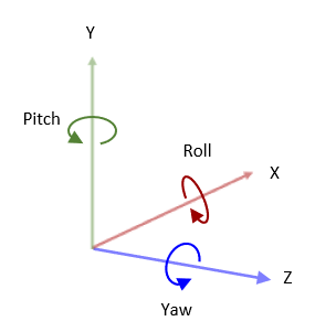
The simulation environment uses a right-handed Cartesian world coordinate system defined in ISO 8855[1]. In this coordinate system:
When facing the positive X-axis, the positive Y-axis points to the left.
The positive Z-axis points upward from the ground.
Yaw, pitch, and roll angles have clockwise-positive directions when looking in the positive directions of the Z-, Y-, and X-axes, respectively.
Note
The Unreal Editor uses a left-handed world Cartesian coordinate system in which the positive Y-axis points right with respect to the positive X-axis. If you are converting from the Unreal Editor coordinate system to the coordinate system of the 3D environment, you must reverse the signs of the Y-axis, pitch angle, and yaw angle.
World coordinate system is fixed and centered on the Unreal Engine scene origin.
This figure illustrates how the Simulation 3D UAV Vehicle block uses this coordinate system to determine the UAV location and orientation in the US City Block scene. The Translation inputs specifies the position of each UAV relative to the scene origin, and the Rotation input specifies the orientation of the vehicle frame of each UAV relative to the world coordinate system.
![Red, green, and blue UAVs placed in the unreal world scene. The red UAV has translation coordinates of [150, 25, 30], The green UAV has translation coordinates of [-50 100 30], and the blue UAV has translation coordinates of [-150 --50 30].](worldcoordinateexample.png)
Vehicle Coordinate System
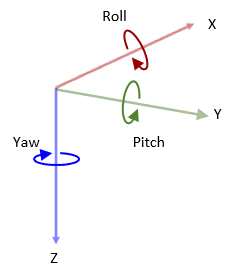
The vehicle coordinate system is based on the world coordinate system and follows the ISO 8855. The coordinate system is fixed to the UAV. In this coordinate system:
The X-axis points forward from the vehicle.
The Y-axis points to the left of the vehicle.
The Z-axis points up from the ground.
Roll, pitch, and yaw are clockwise-positive when looking in the forward direction of the X-, Y-, and Z-axes, respectively.
UAV Toolbox uses the frame rotation angles between the world and vehicle frame in a ZYX (yaw-pitch-roll) rotation sequence to determine the orientation of the UAV.
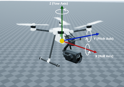
This figure illustrates the vehicle coordinate system of a Quadrotor vehicle.
Sensor Coordinate System
You can add a sensor to your UAV scenario simulation as one of these blocks:
When you add a sensor to the scenario, you can choose to mount the sensor relative to
the scene origin or the UAV origin by specifying its Mounting
Location parameter. If you specify the parameter as scene
origin, the sensor remains stationary during the simulation. If you
specify the parameter as a vehicle name, then the sensor attaches to the specified UAV.
In addition, you can specify the relative translation and rotation of the sensor with
respect to the scene or vehicle origin by specifying the Relative translation
[X, Y, Z] and Relative rotation [Roll, Pitch, Yaw]
parameters, respectively.
By default, the sensor output, relative translation, and relative rotation are specified in ISO8855 coordinate system. However, you can choose a different coordinate system using the Coordinate system parameter of the sensor. This table illustrates the different coordinate systems you can choose for sensors:
| Coordinate System | Block Parameter Option | Description | |
|---|---|---|---|
| Unreal Editor coordinate system | Default | The Unreal Editor coordinate system is a left-handed Cartesian coordinate system, with units in meter and radians. Axes
Rotation
|
|
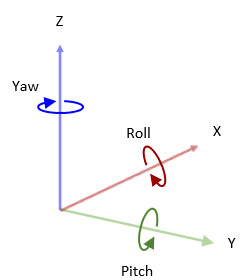
| MATLAB® coordinate system | MATLAB | The MATLAB coordinate system is a right-handed Cartesian coordinate system with Z-up orientation, with units in meter and radians. Axes
Rotation
|
|
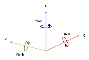
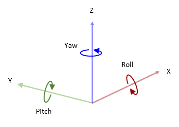
| ISO 8855 standard coordinate system | ISO8855 | The ISO 8855 standard coordinate system is a right-handed Cartesian coordinate system with Z-up orientation, with units in meter and radians. This coordinate system is defined in the ISO 8855 standard. Axes
Rotation
|
|
| X3D ISO standard coordinate system | VRML | The X3D ISO standard coordinate system is a right-handed Cartesian coordinate system with Y-up orientation, with units in meter and radians. Axes
Rotation
|
|
| SAE coordinate system | SAE or AERO | The SAE J670 [2] standard coordinate system is a right-handed Cartesian coordinate system with Z-down orientation, with units in meter and radians. This coordinate system is defined in the SAE J670 standard, and is used for aerospace applications. Axes
Rotation
|
|
References
[1] Technical Committee. Road vehicles — Vehicle dynamics and road-holding ability — Vocabulary. ISO 8855:2011. Geneva, Switzerland: International Organization for Standardization, 2011.
[2] Vehicle Dynamics Standards Committee. Vehicle Dynamics Terminology. SAE J670. Warrendale, PA: Society of Automotive Engineers, 2008.
See Also
Fixed Wing Aircraft | Quadrotor