Evaluate Transitions
Stateflow® uses transitions in charts to move from one exclusive (OR) state to another
exclusive (OR) state. For the entry and execution
workflows of chart execution, Stateflow evaluates transitions to determine if they are valid. A valid transition is a
transition whose condition labels are true and whose path ends at a state. If a transition
is valid, Stateflow exits from the source state and enters the destination state. To learn about
when evaluation occurs during the execution and entry
workflows, see Execution of a Stateflow Chart and Enter a Chart or State.
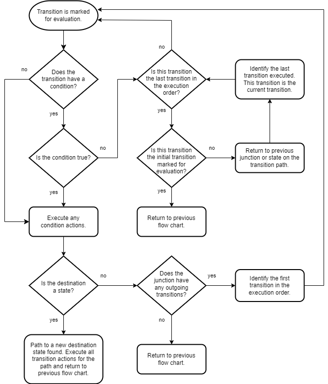
Workflow for Evaluating Transitions
Transition Evaluation Order
When multiple transitions originate from a single source, such as a state or junction, Stateflow uses evaluation order to determine when to test each transition. The number near the source of the transition is the transition order.
Outgoing transitions from a source are automatically numbered in the order in which
you create them. The order starts with 1 and continues to the next
available number for the source.
To change the execution order of a transition, right-click the transition, click Execution Order, and select the order in which you want the transition to execute. When you change a transition number, the Stateflow chart automatically renumbers the other outgoing transitions for the source by preserving their relative order.
Transition to the Inner Edge of a Parent State
Transitions that end on the inside edge of a parent state are a shortcut back to the
default transition path, and the default path is evaluated during the current time step.
In this example, the transition from state B leads immediately to the
default transition to state A.
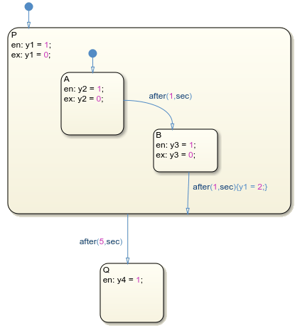
If there are default transitions, then Stateflow immediately executes those paths. If not, and there are no children, then that is the end of the time step. In both cases, the parent remains active, and exit and entry actions of the parent are not executed.
Evaluate Outer Transition
In this example, the Stateflow chart is initialized and the entry actions are
performed for StateA. A new time step occurs and the chart wakes up.
By following the Workflow for Stateflow Chart Execution, Stateflow finds multiple outer transition paths from StateA. At
this time step x = 1, y = 1, and z =
1.
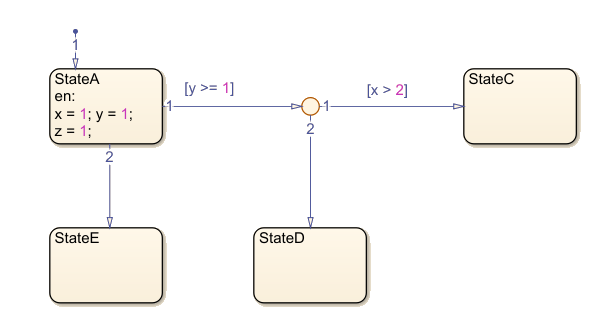
By following the Workflow for Evaluating Transitions, the steps for evaluating the transitions of this chart are in this order:
Transition 1 from
StateAis marked for evaluation.Transition 1 from
StateAhas a condition.The condition is true.
The destination of transition 1 from
StateAis not a state.The junction does have outgoing transitions.
Transition 1 from the junction is marked for evaluation.
Transition 1 from the junction has a condition.
The condition is false.
Transition 2 from the junction is marked for evaluation.
Transition 2 from the junction does not have a condition.
The destination of transition 2 from the junction is a state (
StateD).StateDis marked forentry, andStateAis marked forexit.
To complete the time step, follow the Workflow for Exiting a State for
StateA and the Workflow for Entering a Chart or State for
StateE.
Evaluate Outer Transition with Backtracking
When all outgoing transitions from a source are invalid or do not end with a terminating junction, but there are previously unevaluated transitions, Stateflow returns to the previous state or junction to evaluate all possible paths.
In this example, the Stateflow chart is initialized and the entry actions are
performed for StateA. A new time step occurs, and the chart wakes up.
By following the Workflow for Stateflow Chart Execution, Stateflow finds multiple outer transition paths from StateA. At
this time step x = 1, y = 1, and z =
1.
![]()
By following the Workflow for Evaluating Transitions, the steps for evaluating the transitions of this chart are in this order:
Transition 1 from
StateAis marked for evaluation.Transition 1 from
StateAhas a condition.The condition is true.
The destination of transition 1 from
StateAis not a state.The junction does have outgoing transitions.
Transition 1 from the junction is marked for evaluation.
Transition 1 from the junction has a condition.
The condition is false.
Transition 2 from the junction is marked for evaluation.
Transition 2 from the junction has a condition.
The condition is false.
Transition 2 from
StateAis marked for evaluation.Transition 2 from
StateAdoes not have a condition.The destination of transition 2 from
StateAis a state (StateE).StateEis marked forentry, andStateAis marked forexit.
To complete the time step, follow the Workflow for Exiting a State for
StateA and the Workflow for Entering a Chart or State for
StateE.
Prevent Backtracking
In this example, a terminating junction prevents backtracking. The Stateflow chart is initialized and the entry actions are
performed for StateA. A new time step occurs and the chart wakes
up. By following the Workflow for Stateflow Chart Execution, Stateflow finds multiple outer transition paths from StateA.
At this time step x = 1, y = 1, and z
= 1.
![]()
By following the Workflow for Evaluating Transitions, the steps for evaluating the transitions of this chart are in this order:
Transition 1 from
StateAis marked for evaluation.Transition 1 from
StateAhas a condition.The condition is true.
The destination of transition 1 from
StateAis not a state.The junction does have outgoing transitions.
Transition 1 from the junction is marked for evaluation.
Transition 1 from the junction has a condition.
The condition is false.
Transition 2 from the junction is marked for evaluation.
Transition 2 from the junction has a condition.
The condition is false.
Transition 3 from the junction is marked for evaluation.
Transition 3 from the junction does not have a condition.
The destination is not a state and does not have any outgoing transitions.
Return to Workflow for Stateflow Chart Execution.
To complete the time step, follow the Workflow for Stateflow Chart Execution for
StateA, starting where you left off.
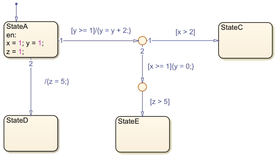
Evaluate Outer Transitions with Condition and Transition Actions
This example contains both condition actions and transition actions:
In transition label syntax, condition actions follow the transition condition and are enclosed in curly braces (
{}). Condition actions are executed when the condition is evaluated as true but before the transition path has been determined to be valid.In transition label syntax, transition actions are preceded with a forward slash (
/) and are enclosed in curly braces ({}). Transition actions execute only after the transition path is determined to be valid.
The Stateflow chart is initialized and the entry actions are
performed for StateA. A new time step occurs and the chart wakes up.
There are multiple outer transition paths from StateA. At this time
step x = 1, y = 1, and z =
1.
By following the Workflow for Evaluating Transitions, the steps for evaluating the transitions of this chart are in this order:
Transition 1 from
StateAis marked for evaluation.Transition 1 from
StateAhas a condition ([y >= 1]).The condition is true.
There are no condition actions.
The destination of transition 1 from
StateAis not a state.The junction does have outgoing transitions.
Transition 1 from the junction is marked for evaluation.
Transition 1 from the junction has a condition (
[x > 2]).The condition is false.
Transition 2 from the junction is marked for evaluation.
Transition 2 from the junction has a condition (
[x >= 1]).The condition is true.
There is a condition action (
{y = 0;}). Nowy = 0.The junction does have outgoing transitions.
The transition from the junction is marked for evaluation.
Transition 1 from the junction has a condition (
[z > 5]).The condition is false.
Transition 2 from
StateAis marked for evaluation.Transition 2 from
StateAdoes not have a condition.The destination of transition 2 from
StateAis a state (StateD).StateDis marked forentry, andStateAis marked forexit. Execute the transition action for this valid path (/{z = 5}). Nowz = 5.
To complete the time step, follow the Workflow for Exiting a State for
StateA and the Workflow for Entering a Chart or State for
StateE.