Solar PV Controller (Three-Phase)

Libraries:
Simscape /
Electrical /
Control /
Renewables Control
Description
The Solar PV Controller (Three-Phase) block implements a photovoltaic (PV) grid-following (GF) controller that uses a maximum power point tracking (MPPT) algorithm. The inputs to the block are the:
Per-unit reactive power reference Qref
DC-side current in amps ipv
DC-side voltage in volts vdc
AC-side per-unit voltage vabc
AC-side per-unit current iabc
The outputs of the block are the per-unit reference voltage wave for the solar inverter vabcRef and a bus containing signals for visualization. This figure shows the top-level structure of the controller.
The Volt-VAR controller calculates the per-unit q-axis current reference iq ref.
The MPPT algorithm calculates the DC-side reference voltage Vdc ref in volts.
The DC voltage controller calculates the per-unit d-axis current reference id ref.
The phase-locked loop (PLL) calculates the:
Phase angle θ of the input voltage signal vabc
Per-unit d-axis voltage Vd
Per-unit q-axis voltage Vq
The Park transform converts iabc and θ into the:
Per-unit d-axis current id
Per-unit q-axis current iq
The current controller calculates the:
Per-unit d-axis voltage reference Vd ref
Per-unit q-axis voltage reference Vq ref
The inverse Park transform converts Vd ref and Vq ref into vabcRef.
For discrete-time simulation, set Sample time (-1 for inherited) to a
positive value or to -1 to inherit the sample time. For continuous-time
simulation, set Sample time (-1 for inherited) to
0.
To choose the MPPT algorithm, in the MPPT tab, set the Algorithm parameter to one of these options:
Perturb and observe (P&O)— The P&O algorithm perturbs the operating voltage of the solar panel. The algorithm then observes the change in power output. If the power increases, the perturbation continues in the same direction. If the power decreases, the algorithm reverses the perturbation. To prioritize simulation speed, use this option.Incremental conductance (INC)— The INC algorithm calculates the incremental change in current and voltage to determine the slope of the power-voltage curve. If the slope is positive, the operating point moves to a higher voltage. If the slope is negative, the operating point moves to a lower voltage. If the slope is close to zero, the algorithm has reached the maximum power point (MPP). To prioritize accuracy in tracking the MPP, use this option.
Visualization
The block outputs a bus containing these nine signals for visualization:
Estimated phase angle θ of the input voltage signal vabc
DC-side voltage Vdc in volts
Per-unit q-axis current reference iq ref
Per-unit d-axis current reference id ref
DC-side reference voltage Vdc ref in volts
Per-unit d-axis voltage Vd
Per-unit q-axis voltage Vq
Per-unit d-axis current id
Per-unit q-axis current iq
Examples
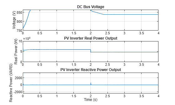
Control Three-Phase Solar Inverter
Control a three-phase single-stage solar photovoltaic (PV) inverter using a Solar PV Controller (Three-Phase) block. In a grid-connected PV plant, a PV controller extracts the maximum power from the solar array and feeds it to the grid. To extract the maximum available PV power, the controller uses a maximum power point tracking (MPPT) algorithm.
Ports
Input
Output
Parameters
Extended Capabilities
Version History
Introduced in R2024a