DC Motor
DC motor model with electrical and torque characteristics and fault modeling
Libraries:
Simscape /
Electrical /
Electromechanical /
Brushed Motors
Description
The DC Motor block represents the electrical and torque characteristics of a DC motor using this equivalent circuit model.
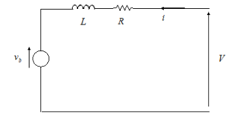
You specify the equivalent circuit parameters for this model when you set the
Model parameterization parameter to By equivalent
circuit parameters. The resistor R corresponds to
the resistance you specify in the Armature resistance parameter.
The inductor L corresponds to the inductance you specify in the Armature
inductance parameter.
You can specify how to generate the magnetic field of the DC motor by setting the Field type parameter to the desired option. The permanent magnets in the motor induce the following back emf vb in the armature:
where kv is the Back-emf constant and ω is the angular velocity. The motor produces the following torque, which is proportional to the motor current i:
where kt is the Torque constant. The DC Motor block assumes that there are no electromagnetic losses. This means that mechanical power is equal to the electrical power dissipated by the back emf in the armature. Equating these two terms gives:
As a result, you specify either kv or kt in the block parameters.
If the magnetic field is generated from the current flowing through the windings, the Back-emf constant depends on the field current If:
where Laf is the Field-armature mutual inductance.
The torque-speed characteristic for the DC Motor block
is related to the parameters in the preceding figure. When you set the Model
parameterization parameter to By stall torque & no-load
speed or By rated load and speed, the block
solves for the equivalent circuit parameters as follows:
For the steady-state torque-speed relationship, L has no effect.
Sum the voltages around the loop and rearrange for i:
Substitute this value of i into the equation for torque:
When you set the Model parameterization parameter to
By stall torque & no-load speed, the block uses the stall torque and no-load speed to determine values for R and kt (and equivalently kv).When you set the Model parameterization parameter to
By rated load and speed, the block uses the rated speed and power to calculate the rated torque. The block uses the rated torque and no-load speed values to determine values for R and kt.
The block models motor inertia J and damping λ for all values of the Model parameterization parameter. The resulting torque across the block is:
It is not always possible to measure rotor damping, and rotor damping is not always provided on a manufacturer datasheet. An alternative is to use the no-load current to infer a value for rotor damping.
For no-load, the electrically-generated mechanical torque must equal the rotor damping torque:
where inoload is the no-load current. If you
select By no-load current for the Rotor damping
parameterization parameter, then this equation is used in addition to the
torque-speed equation to determine values for λ and the other
equation coefficients.
The value for rotor damping, whether specified directly or in terms of no-load
current, is taken into account when determining equivalent circuit parameters for
Model parameterization options By stall torque and
no-load speed and By rated load and
speed.
When a positive current flows from the electrical + to - ports, a positive torque acts from the mechanical C to R ports.
Note
Simscape™ Electrical™ includes several blocks that can model the same type of motor or actuator. Choose a block that has sufficient modeling detail for the engineering design questions that you need to answer. Do not use a block that has more modeling detail than you need, because higher-fidelity models slow down simulation and are more complex to parameterize.
Blocks like the DC Motor block model motors with fixed or parameter-dependent coefficients with a simple equivalent circuit. These models have an intermediate level of fidelity. Use this block to design controls or systems in actuation applications, such as robotics and mechatronics, and for efficiency predictions when saturation and harmonics only weakly impact losses. For more information about choosing the right block to model your motor at the right level of fidelity, see Choose Blocks to Model Motors or Actuators.
Faults
To model a fault in the DC Motor block, in the Faults section, click Add fault next to the fault that you want to model. For more information about fault modeling, see Fault Behavior Modeling and Fault Triggering.
The DC Motor block allows you to model two types of faults:
Armature winding fault — The armature winding fails and goes open circuit.
Field winding fault — The field winding that creates the magnetic field fails and goes open circuit.
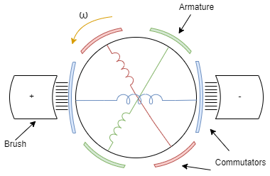
This figure shows a generic representation of a DC motor, with brushes, armatures, commutators, and their windings:
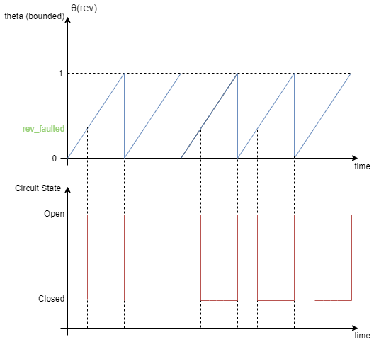
When the armature fails, the voltage source connected to this block observes an
open circuit for a fraction of the total motor revolution, specified by the
Fraction of revolution during which armature is
open-circuit parameter, rev_faulted. This figure
illustrates the circuit state behavior for a certain rev_faulted
during the entire revolution period:
You specify how and when faults occur by using the Trigger type parameter.
If you set the Trigger type to
Behavioral, the DC Motor block triggers faults
when the winding currents continuously exceed a threshold value for longer than
a specific time interval:
Armature winding faults occur when the winding currents continuously exceed the value of the Maximum permissible armature winding current parameter for a duration longer than the value of the Time to fail when exceeding armature winding current parameter.
Field winding faults occur when the winding currents exceed the value of the Maximum permissible field winding current parameter for a duration longer than the value of the Time to fail when exceeding field winding current parameter.
If you set the Trigger
type to Conditional, you can choose whether faults
in the DC Motor block are reversible (since R2025a). To model irreversible faults, click
Open fault properties to open the Property Inspector and select the
Trigger stays on once activated parameter. The block enters the faulted
state when the trigger condition becomes true for the first time and remains in the faulted
state for the rest of the simulation. To model reversible faults, clear the Trigger
stays on once activated parameter. The block enters the faulted state when the
trigger condition is true and enters the unfaulted state when the trigger condition is
false.
For more information about adding faults to blocks and specifying fault triggers, see Introduction to Simscape Faults.
Predefined Parameterization
There are multiple available built-in parameterizations for the permanent magnet
DC Motor block. To select a parameterization, set the Model
Parameterization parameter to By equivalent circuit
parameters.
This pre-parameterization data allows you to set up the block to represent components by specific suppliers. The parameterizations of these DC motors match the manufacturer data sheets. To load a predefined parameterization, double-click the DC Motor block, click the <click to select> hyperlink of the Selected part parameter and, in the Block Parameterization Manager window, select the part you want to use from the list of available components.
Note
The predefined parameterizations of Simscape components use available data sources for the parameter values. Engineering judgment and simplifying assumptions are used to fill in for missing data. As a result, expect deviations between simulated and actual physical behavior. To ensure accuracy, validate the simulated behavior against experimental data and refine component models as necessary.
For more information about pre-parameterization and for a list of the available components, see Simscape Electrical Part Collection.
Model Thermal Effects
You can expose the thermal port to model the effects of losses that convert power to heat. To expose the thermal port, set the Modeling option parameter to either:
No thermal port— The block does not contain a thermal port.Show thermal port— The block contains one thermal conserving port.
For more information about using thermal ports in actuator blocks, see Simulating Thermal Effects in Rotational and Translational Actuators.
Examples

Linear Electric Actuator (Motor Model)
How to develop a model of an uncontrolled linear actuator using datasheet parameter values. The actuator consists of a DC motor driving a 6.25:1 worm gear which in turn drives a 3mm lead screw to produce linear motion. Manufacturer data for the actuator defines the no-load linear speed (26mm/s), rated load (1000N), rated-load linear speed (19mm/s), and maximum current (5A). The maximum static force is 4000N and the rated voltage is 24V DC.
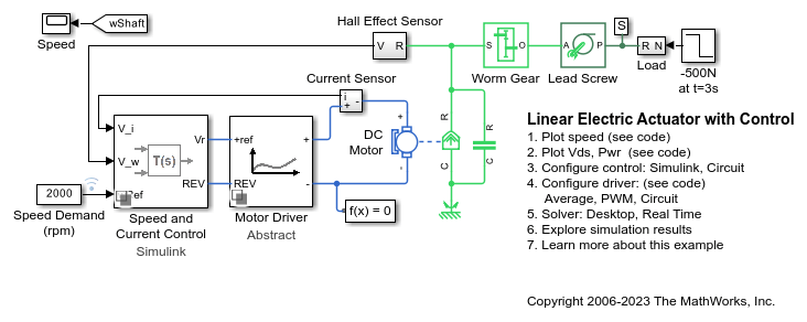
Linear Electric Actuator with Control
A detailed implementation model of a controlled linear actuator. The actuator consists of a DC motor driving a worm gear which in turn drives a lead screw to produce linear motion. The model includes quantization effects of the Hall-effect sensor and the implementation of the control in analog electronics. There are multiple variant subsystems in this model that have models at varying levels of fidelity.

Control DC Motor with PWM Voltage Source and H-Bridge Driver
Control a DC motor by using the Controlled PWM Voltage and H-Bridge blocks. The DC Motor block delivers a mechanical power of 10 W at 2500 rpm and turns at a no-load speed of 4000 rpm when the DC supply voltage is 12 V. Consequently, if you set the PWM reference voltage to its maximum value of 5 V, the motor runs at 4000 rpm. If you set the PWM reference voltage to 2.5 V, the motor runs at approximately 2000 rpm. To achieve fast simulation, this example sets the Simulation mode parameter of the Controlled PWM Voltage and H-Bridge blocks to Averaged. To validate the averaged behavior, set the Simulation mode parameter to PWM in both the Controlled PWM Voltage and H-Bridge blocks.

Motor Torque-Speed Curves
A comparison of the torque-speed characteristics for five different motor types. To select the motor type, right-click on the Electric Motor block and select Block Parameters (Subsystem) from the context menu. In the new window, specify the desired motor using the Label mode active choice parameter. All motors have been sized for roughly the same mechanical power rating.

DC Motor Control
A cascade speed-control structure for a DC motor. A PWM controlled four-quadrant Chopper is used to feed the DC motor. The Control subsystem includes the outer speed-control loop, the inner current-control loop, and the PWM generation. The total simulation time (t) is 4 seconds. At t = 1.5 seconds, the load torque increases. At t = 2.5 seconds, the reference speed is changed from 1000 rpm to 2000 rpm.
Design PID Control for DC Motor Using Classical Control Theory
Design a PID controller for a DC Motor using classical control theory. Alternatively, you can use Steady State Manager, Model Linearizer, Frequency Response Estimator, or PID tuner apps to streamline the design.
Ports
Conserving
Parameters
References
[1] Bolton, W. Mechatronics: Electronic Control Systems in Mechanical and Electrical Engineering, 3rd edition Pearson Education, 2004.