Simulating Thermal Effects in Rotational and Translational Actuators
Using the Thermal Ports
All blocks that represent rotational and translational actuators with electrical windings can optionally show a thermal port for each electrical winding. So, for example:
A DC Motor block can optionally show a single thermal port corresponding to the armature
A Shunt Motor block can optionally show two thermal ports, one for the stator winding and one for the field winding
The thermal port represents copper resistance losses which convert electrical power to heat. These losses are sometimes referred to as i2R losses. Some blocks include models for iron losses due to Eddy currents and hysteresis. If iron loss models are included, they are accounted in the heat in the thermal port.
The thermal ports are hidden by default. To expose the thermal port on a particular block instance in your block diagram:
Double-click the block where you want to show the thermal port.
Set the Modeling option parameter to
Show thermal
                port
.
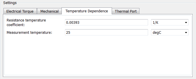
When the thermal port is exposed, the block dialog box contains two additional tabs, Temperature Dependence and Thermal Port. For actuator blocks with single winding, these tabs always contain the same set of parameters.

Resistance temperature coefficient — Parameter α in the equation defining resistance as a function of temperature, as described in Thermal Model for Actuator Blocks. The default value is for copper, and is
0.003931/K.Measurement temperature — The temperature for which motor parameters are defined. The default value is
25°C.

Thermal mass — Thermal mass of the electrical winding, defined as the energy required to raise the temperature by one degree. The default value is
100J/K.Initial temperature — The temperature of the thermal port at the start of simulation. The default value is
25°C.
For more information on selecting the parameter values, see Thermal Model for Actuator Blocks.
Parameters for actuator blocks with two windings differ, and are described on the respective block reference pages.
Thermal Model for Actuator Blocks
The following illustration shows the thermal port model used by the actuator blocks. The heat generated by the copper windings is provided as an input to the S physical signal input port of the Ideal Heat Flow Source. The thermal mass represents the lumped thermal mass of the copper winding where thermal mass is defined as the energy required to raise its temperature by one degree. If the mass is denoted M and the specific heat capacity is cp, then thermal mass is M·cp.

Winding resistance is assumed linearly dependent on temperature, and is given by:
R = R0 (1 + α (T – T0 ))
where:
R is the resistance at temperature T.
R0 is the resistance at the measurement (or reference) temperature T0.
α is the resistance temperature coefficient. A typical value for copper is 0.00393/K.