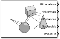
Simulation 3D Ray Tracer
Libraries:
Vehicle Dynamics Blockset /
Vehicle Scenarios /
Sim3D /
Sim3D Vehicle /
Components
Simulink 3D Animation /
Simulation 3D /
Sensors
Description
The Simulation 3D Ray Tracer block implements ray tracing to get the positions, surface normals, surface identifiers, and distances for objects in the scene. You can specify block parameters that configure the ray origins, directions, and lengths to adjust the ray trace sensor pattern for your scene and test scenario.
Tip
Verify that the Simulation 3D Scene Configuration block executes before the Simulation 3D Ray Tracer block. That way, the Unreal Engine® 3D visualization environment prepares the data before the Simulation 3D Ray Tracer block receives it. To check the block execution order, right-click the blocks and select Properties. On the General tab, confirm these Priority settings:
Simulation 3D Scene Configuration —
0
Simulation 3D Terrain Sensor —
1
For more information about execution order, see Control and Display Execution Order (Simulink).
Ports
Output
HitLocations — Hit locations
real-valued N(B+1)-by-3 array
Hit locations, returned as a real-valued N(B+1)-by-3 array of the form [X, Y, Z], in meters. N is the number of rays and B is the number of bounces per ray.
If you mount the sensor to a vehicle by setting Parent name to the name of that vehicle, then X, Y, and Z are in the 3D visualization engine coordinate system, where:
The X-axis points forward from the vehicle
The Y-axis points to the right of the vehicle, as viewed when looking in the forward direction of the vehicle
The Z-axis points up
Data Types: double
HitNormals — Ray normal to hit location
real-valued N(B+1)-by-3 array
Ray normal to the hit location, returned as a real-valued N(B+1)-by-3 array of the form [X, Y, Z], in meters. N is the number of rays and B is the number of bounces per ray.
If you mount the sensor to a vehicle by setting Parent name to the name of that vehicle, then X, Y, and Z are in the 3D visualization engine coordinate system, where:
The X-axis points forward from the vehicle
The Y-axis points to the right of the vehicle, as viewed when looking in the forward direction of the vehicle
The Z-axis points up
Data Types: double
HitDistances — Ray distance to hit location
real-valued N(B+1)-by-1 array
Ray distance to hit location, returned as a real-valued N(B+1)-by-1 vector N, in meters. N is the number of rays and B is the number of bounces per ray.
Data Types: double
SurfaceIds — Object IDs of hit surfaces
integer-valued N(B+1)-by-1 vector | 0
Object identifier of the surfaces hit by the ray, returned as an integer-valued N(B+1)-by-1 vector N. N is the number of rays and B is the number of bounces per ray.
The returned surface identifiers are the object values specified when creating
custom surfaces in the Unreal® Editor. If a surface identifier is unknown, the block assigns it an ID
of 0
. For information about adding surfaces, see Add a Surface Type in the Unreal Engine documentation.
Data Types: uint8
IsValidHit — Hit flag
N-by-1 vector
Hit flag, returned as a N-by-1 Boolean vector. N is the number of rays. A value of 1 indicates the ray hit a surface.
Data Types: Boolean
Parameters
Sensor identifier — Unique sensor identifier
1
(default) | positive integer
Specify the unique identifier of the sensor. In a multisensor system, the sensor identifier enables you to distinguish between sensors. When you add a new sensor block to your model, the Sensor identifier of that block is N + 1, where N is the highest Sensor identifier value among the existing sensor blocks in the model.
Example: 2
Parent name — Name of parent
Scene Origin
(default)
Name of parent to which the sensor is mounted, specified as the name of a vehicle in
your model, or Scene Origin
. The vehicle names that you can
select correspond to the Name parameters of the
simulation 3D vehicle blocks in your model.
Mounting location — Sensor mounting location
Origin
(default) | Front bumper
| Rear bumper
| Right mirror
| Left mirror
| Rearview mirror
| Hood center
| Roof center
| ...
Sensor mounting location.
When Parent name is
Scene Origin
, the block mounts the sensor to the origin of the scene. You can set the Mounting location toOrigin
only. During simulation, the sensor remains stationary.When Parent name is the name of a vehicle, the block mounts the sensor to one of the predefined mounting locations described in the table. During simulation, the sensor travels with the vehicle.
Vehicle Mounting Location | Description | Orientation Relative to Vehicle Origin [Roll, Pitch, Yaw] (deg) |
---|---|---|
Origin | Forward-facing sensor mounted to the vehicle origin, which is on the ground and at the geometric center of the vehicle (see Coordinate Systems for Unreal Engine Simulation in Automated Driving Toolbox (Automated Driving Toolbox)) | [0, 0, 0] |
| Forward-facing sensor mounted to the front bumper | [0, 0, 0] |
| Backward-facing sensor mounted to the rear bumper | [0, 0, 180] |
Right mirror | Downward-facing sensor mounted to the right side-view mirror | [0, –90, 0] |
Left mirror | Downward-facing sensor mounted to the left side-view mirror | [0, –90, 0] |
Rearview mirror | Forward-facing sensor mounted to the rearview mirror, inside the vehicle | [0, 0, 0] |
Hood center | Forward-facing sensor mounted to the center of the hood | [0, 0, 0] |
Roof center | Forward-facing sensor mounted to the center of the roof | [0, 0, 0] |
Roll, pitch, and yaw are clockwise-positive when looking in the positive direction of the X-axis, Y-axis, and Z-axis, respectively. When looking at a vehicle from above, the yaw angle (the orientation angle) is counterclockwise-positive because you are looking in the negative direction of the axis.
The X-Y-Z mounting location of the sensor relative to the vehicle depends on the vehicle type. To specify the vehicle type, use the Type parameter of the Simulation 3D Vehicle with Ground Following to which you mount the sensor. To obtain the X-Y-Z mounting locations for a vehicle type, see the reference page for that vehicle.
To determine the location of the sensor in world coordinates, open the sensor block. Then, on the Ground Truth tab, select the Output location (m) and orientation (rad) parameter and inspect the data from the Translation output port.
Specify offset — Specify offset from mounting location
off
(default) | on
Select this parameter to specify an offset from the mounting location by using the Relative translation [X, Y, Z] (m) and Relative rotation [Roll, Pitch, Yaw] (deg) parameters.
Relative translation [X, Y, Z] (m) — Translation offset relative to mounting location
[0, 0, 0]
(default) | real-valued 1-by-3 vector
Translation offset relative to the mounting location of the sensor, specified as a real-valued 1-by-3 vector of the form [X, Y, Z], in meters.
If you mount the sensor to a vehicle by setting Parent name to the name of that vehicle, then X, Y, and Z are in the vehicle coordinate system, where:
The X-axis points forward from the vehicle
The Y-axis points to the left of the vehicle, as viewed when looking in the forward direction of the vehicle
The Z-axis points up
The origin is the mounting location specified in the Mounting location parameter. This origin is different from the vehicle origin, which is the geometric center of the vehicle.
If you mount the sensor to the scene origin by setting Parent
name to Scene Origin
, then
X, Y, and Z are in the
world coordinates of the scene.
For more details about the vehicle and world coordinate systems, see Coordinate Systems in Vehicle Dynamics Blockset (Vehicle Dynamics Blockset).
Example: [0,0,0.01]
Dependencies
To enable this parameter, select Specify offset.
Relative rotation [Roll, Pitch, Yaw] (deg) — Rotational offset relative to mounting location
[0, 0, 0]
(default) | real-valued 1-by-3 vector
Rotational offset relative to the mounting location of the sensor, specified as a real-valued 1-by-3 vector of the form [Roll, Pitch, Yaw], in degrees. Roll, pitch, and yaw are the angles of rotation about the X-, Y-, and Z-axes, respectively.
If you mount the sensor to a vehicle by setting Parent name to the name of that vehicle, then X, Y, and Z are in the vehicle coordinate system, where:
The X-axis points forward from the vehicle.
The Y-axis points to the left of the vehicle, as viewed when looking in the forward direction of the vehicle.
The Z-axis points up.
Roll, pitch, and yaw are clockwise-positive when looking in the forward direction of the X-axis, Y-axis, and Z-axis, respectively. If you view a scene from a 2D top-down perspective, then the yaw angle (also called the orientation angle) is counterclockwise-positive because you are viewing the scene in the negative direction of the Z-axis.
The origin is the mounting location specified in the Mounting location parameter. This origin is different from the vehicle origin, which is the geometric center of the vehicle.
If you mount the sensor to the scene origin by setting Parent
name to Scene Origin
, then
X, Y, and Z are in the
world coordinates of the scene.
For more details about the vehicle and world coordinate systems, see Coordinate Systems in Vehicle Dynamics Blockset (Vehicle Dynamics Blockset).
Example: [0,0,10]
Dependencies
To enable this parameter, select Specify offset.
Ray origins — Ray origin
zeros(10,3)
(default) | real-valued N-by-3 array
Ray origin relative to sensor mounting location, specified as a real-valued N-by-3 array of the form [X, Y, Z], in meters. N is the number of rays.
If you mount the sensor to a vehicle by setting Parent name to the name of that vehicle, then X, Y, and Z are in the 3D visualization engine coordinate system, where:
The X-axis points forward from the vehicle
The Y-axis points to the right of the vehicle, as viewed when looking in the forward direction of the vehicle
The Z-axis points up
Example: zeros(10,3)
Ray directions — Normalized ray direction
ones(10,3)
(default) | real-valued N-by-3 array
Normalized ray direction relative to sensor mounting location, specified as a real-valued N-by-3 array of the form [X, Y, Z]. N is the number of rays. The units are dimensionless.
If you mount the sensor to a vehicle by setting Parent name to the name of that vehicle, then X, Y, and Z are in the 3D visualization engine coordinate system, where:
The X-axis points forward from the vehicle
The Y-axis points to the right of the vehicle, as viewed when looking in the forward direction of the vehicle
The Z-axis points up
Example: ones(10,3)
Max ray lengths — Maximum total ray length
ones(10,1)*10
(default) | real-valued N-by-1 vector
Maximum total ray length of a multi-bounce trace path, specified as a real-valued N-by-1 vector, in meters. N is the number of rays.
Example: ones(10,1)*10
Number of bounces — Number of bounces per ray
2
(default) | positive integer
Number of bounces that a trace may have before terminating, B, specified as an integer.
Example: 0
Visualize trace line — Visualize ray traces
on (default) | off
Whether to enable Unreal Engine trace line visualization for the ray tracer.
Enable optimization — Enable optimization
on (default) | off
Whether to enable optimization of the ray tracer. Enabling this parameter allows the block to perform concurrent traces. Enable this parameter when the number of traces is large and your machine has multiple cores.
Sample time — Sample time
-1
(default) | positive scalar
Sample time of the block, in seconds, specified as a positive scalar. The 3D simulation environment frame rate is the inverse of the sample time.
If you set the sample time to -1
, the block inherits its sample time from
the Simulation 3D Scene Configuration block.
Version History
Introduced in R2024a
MATLAB Command
You clicked a link that corresponds to this MATLAB command:
Run the command by entering it in the MATLAB Command Window. Web browsers do not support MATLAB commands.
Select a Web Site
Choose a web site to get translated content where available and see local events and offers. Based on your location, we recommend that you select: .
You can also select a web site from the following list
How to Get Best Site Performance
Select the China site (in Chinese or English) for best site performance. Other MathWorks country sites are not optimized for visits from your location.
Americas
- América Latina (Español)
- Canada (English)
- United States (English)
Europe
- Belgium (English)
- Denmark (English)
- Deutschland (Deutsch)
- España (Español)
- Finland (English)
- France (Français)
- Ireland (English)
- Italia (Italiano)
- Luxembourg (English)
- Netherlands (English)
- Norway (English)
- Österreich (Deutsch)
- Portugal (English)
- Sweden (English)
- Switzerland
- United Kingdom (English)
Asia Pacific
- Australia (English)
- India (English)
- New Zealand (English)
- 中国
- 日本Japanese (日本語)
- 한국Korean (한국어)