Composite Component — DC Motor
In the Permanent Magnet DC Motor example, the DC Motor block is implemented as a masked subsystem.
The following code implements the same model by means of a composite
component, called DC Motor. The composite component
uses the components from the Simscape™ Foundation library as building
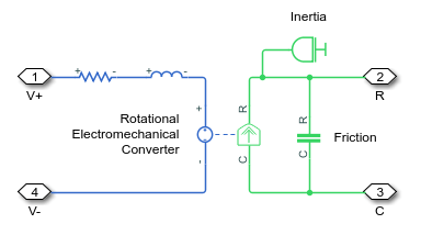
blocks, and connects them as shown in the preceding block diagram.
component DC_Motor
% DC Motor
% This block models a DC motor with an equivalent circuit comprising a
% series connection of a resistor, inductor, and electromechanical converter.
% Default values are the same as for the Permanent Magnet DC Motor example model.
nodes
p = foundation.electrical.electrical; % +:left
n = foundation.electrical.electrical; % -:left
R = foundation.mechanical.rotational.rotational; % R:right
C = foundation.mechanical.rotational.rotational; % C:right
end
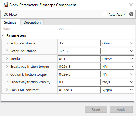
parameters
rotor_resistance = { 3.9, 'Ohm' }; % Rotor Resistance
rotor_inductance = { 12e-6, 'H' }; % Rotor Inductance
motor_inertia = { 0.01, 'g*cm^2' }; % Inertia
breakaway_torque = { 0.02e-3, 'N*m' }; % Breakaway friction torque
coulomb_torque = { 0.02e-3, 'N*m' }; % Coulomb friction torque
breakaway_velocity = { 0.1, 'rad/s' }; % Breakaway friction velocity
back_emf_constant = { 0.072e-3, 'V/rpm' }; % Back EMF constant
end
components(ExternalAccess=observe)
rotorResistor = foundation.electrical.elements.resistor(R = rotor_resistance);
rotorInductor = foundation.electrical.elements.inductor(l = rotor_inductance);
rotationalElectroMechConverter = foundation.electrical.elements.rotational_converter(K = ...
back_emf_constant);
friction = foundation.mechanical.rotational.friction(brkwy_trq = ...
breakaway_torque, Col_trq = coulomb_torque, ...
brkwy_vel = breakaway_velocity);
motorInertia = foundation.mechanical.rotational.inertia(inertia = motor_inertia);
end
connections
connect(p, rotorResistor.p);
connect(rotorResistor.n, rotorInductor.p);
connect(rotorInductor.n, rotationalElectroMechConverter.p);
connect(rotationalElectroMechConverter.n, n);
connect(rotationalElectroMechConverter.R, friction.R, motorInertia.I, R);
connect(rotationalElectroMechConverter.C, friction.C, C);
end
end
The declaration section of the composite component starts with
the nodes section, which defines the top-level
connection ports of the resulting composite block:
Two electrical conserving ports,
+and-, on the left side of the blockTwo mechanical rotational conserving ports,
RandC, on the right side of the block
![]()
The parameters declaration section lists all the parameters that will be
available in the composite block dialog box.
The components section declares all the member (constituent) components,
specifying their complete names starting from the top-level namespace folder. This example
uses the components from the Simscape Foundation library:
Resistor
Inductor
Rotational Electromechanical Converter
Rotational Friction
Inertia
The components section also links the top-level parameters, declared in the
parameters declaration section, to the parameters of underlying member
components. For example, the Rotor Resistance parameter of the composite
block (rotor_resistance) corresponds to the Resistance
parameter (R) of the Resistor block in the Foundation library.
You do not have to link all the parameters of member blocks to top-level parameters. For example, the Rotational Friction block in the Foundation library has the Viscous friction coefficient parameter, which is not mapped to any parameter at the top level. Therefore, the composite model always uses the default value of this parameter specified in the Rotational Friction component, 0.001 N*m/(rad/s).
The connections section defines the connections between the nodes (ports)
of the member components, and their connections to the top-level ports of the resulting
composite block, declared in the nodes declaration section of the composite
component:
Positive electrical port
pof the composite component is connected to the positive electrical portpof the ResistorNegative electrical port
nof the Resistor is connected to the positive electrical portpof the InductorNegative electrical port
nof the Inductor is connected to the positive electrical portpof the Rotational Electromechanical ConverterNegative electrical port
nof the Rotational Electromechanical Converter is connected to the negative electrical portnof the composite componentMechanical rotational port
Rof the composite component is connected to the following mechanical rotational ports:Rof the Rotational Electromechanical Converter,Rof the Rotational Friction, andIof the InertiaMechanical rotational port
Cof the composite component is connected to the following mechanical rotational ports:Cof the Rotational Electromechanical Converter andCof the Rotational Friction
These connections are the textual equivalent of the graphical connections in the preceding block diagram.