NavIC L1 Receiver Positioning
R2026bThis example shows how to estimate the position of a stationary receiver using the Navigation with Indian Constellation (NavIC) L1 standard positioning service (SPS) signal. The example builds a multi-satellite scenario using a NavIC satellite Receiver Independent Exchange (RINEX) file. It then generates the L1-SPS signal for each visible satellite and propagates the signals through a realistic channel with Doppler shift, delay, and noise. The receiver processes the composite signal through a complete chain that performs acquisition, tracking, frame synchronization, data decoding, and position estimation over time.
The NavIC L1 SPS signal operates at a center frequency of 1575.42 MHz and transmits two channels, a pilot channel for acquisition and synchronization, and a data channel that carries the navigation message [1]. Each channel uses a unique spreading code of 10230 chips at 1.023 mega chips per second (Mcps), resulting in a code period of 10 ms.
Example Workflow
The simulation consists of two parts. The transmitter generates signals from multiple NavIC satellites. The receiver processes the signals to recover navigation data and estimate the receiver position.
Transmitter chain
Load orbital parameters from a RINEX file and create a
satelliteScenariowith the visible NavIC satellites.Compute the Doppler shift and propagation delay between each satellite and the receiver at every simulation time step.
Create a navigation data configuration object containing ephemeris and clock parameters extracted from the RINEX file.
Encode the navigation message into data bits as specified by the NavIC L1-SPS standard [1].
Generate the NavIC L1 waveform by spreading the data bits with the L1 data code, generating the pilot channel with the L1 pilot code, and then combining both channels using interplex modulation. For detailed information, see NavIC Waveform Generation example and
interplexmodfunction.Pass the composite signal through a propagation channel that applies the Doppler shift, signal delay, and additive noise.
Receiver Chain
Acquire visible satellites on the pilot channel using
gnssSignalAcquirer, which estimates the coarse Doppler offset and code phase for each detected satellite.Track the pilot and data channels independently using
gnssSignalTrackerobject.Detect the frame boundary by using the
gnssFrameSynchronizerobject to identify the synchronization pattern in the pilot channel symbols.Decode the navigation data from the corresponding data channel symbols.
Compute pseudoranges from the estimated signal transit times, determine position of each satellite from the decoded ephemeris, and estimate the receiver position.
Initialize Simulation Parameters
Initialize the relevant simulation parameters. Specify ShowVisualizations as true to display plots in simulation. You can enable WriteWaveformToFile to save the generated baseband waveform to a file, which you can replay later with another receiver.
ShowVisualizations =false; WriteWaveformToFile =
false;
A NavIC L1 frame spans 18 seconds and consists of 1800 symbols transmitted at a rate of 100 symbols per second. It uses the CNAV-2 frame structure, which enables an 18-second time to first fix (TTFF) after signal acquisition.Therefore, set the simulationDuration to at least 19 seconds to complete the full positioning pipeline. Use a longer duration to obtain additional position estimates.
simulationDuration = 2; % In seconds
% Define sample rate of the generated waveform.
fs = 10e6;              % In Hz
The simulation advances in steps of one code period, which lasts 10 milliseconds. At each step, the transmitter generates one code period of waveform and the receiver processes that chunk through its state machine.
Initialize the receiver position. The propagation channel uses the receiver position at each time step to compute the delay and Doppler for each satellite-receiver link. This example uses a stationary receiver.
rxPos = [17.361786 78.474774 25]; % [latitude (deg) longitude (deg) altitude (m)]A global navigation satellite system (GNSS) signal takes about 120 milliseconds to travel from a satellite in medium-Earth orbit (MEO) to the ground. The receiver must wait at least this duration before it starts processing, otherwise, it processes only noise. Set rxWaitTime so that the first meaningful samples arrive before the receiver begins acquisition.
rxWaitTime = 149e-3; % In secondsInitialize the physical constants and link budget parameters used to compute received signal power and thermal noise.
c = physconst("LightSpeed");
Dt = 12;                                % Transmit antenna directivity (dBi)
DtLin = db2pow(Dt);
Dr = 4;                                 % Receive antenna directivity (dBi)
DrLin = db2pow(Dr);
Pt = 50;                                % Typical transmission power of satellite (watts)
k = physconst("boltzmann");
T = 300;                                % System noise temperature (K)
Nr = k*T*fs;                            % Noise power across the sampling bandwidth
Initialize Waveform Generation Parameters
Specify the parameters required to generate a NavIC L1-SPS waveform, as defined in the NavIC L1 standard [1].
fc = 1575.42e6;                         % Carrier Frequency (Hz)
codeLen = 10230;                        % Length of the spreading code (chips)
bitRate = 100;                          % Navigation data bit rate (bits/s)
chipRate = 1.023e6;                     % Spreading code chip rate (chips/s)
oneCodeDuration = codeLen/chipRate;
oneBitDuration = 1/bitRate;
numCodeBlocksPerBit = oneBitDuration/oneCodeDuration;
Configure Simulation
Configure the simulation using the specified parameters and physical constants. The RINEX file provides the orbital parameters, the satellite scenario propagates the satellite orbits over time, and the navigation configuration object stores the ephemeris and clock parameters required for waveform generation.
A RINEX file may contain multiple sets of navigation data for the same satellite at different epochs. Because this simulation simulates only a short time interval, a single set of orbital parameters is sufficient to model each satellite throughout the simulation. Therefore, extract only the first epoch for each pseudo-random noise identifier (PRN ID). This example uses the NavIC PRN IDs available in the selected RINEX file, which can differ from the operational L1 PRN IDs.
rinexFileName = "IITK00IND_R_20243400400_01H_MN.rnx";
rinexData = rinexread(rinexFileName);
rinexFileInfo = rinexinfo(rinexFileName);

allNavicData = processRinexData(rinexData,rinexFileInfo);

% Keep only the first epoch per PRN and align all timestamps to a common reference
[~,satIdx] = unique(allNavicData.SatelliteID);
navicData = sortrows(allNavicData(satIdx,:),1);

navicData.Time(:) = dateshift(mode(navicData.Time),"start","hour") + minutes(15*floor(minute(mode(navicData.Time))/15));

% Create a navigation data configuration object using the RINEX file.
navConfig = HelperNavICRINEX2Config(navicData,"NavIC L1-SPS");
Configure the satellite scenario with the required parameters from the RINEX file.
stepTime = oneCodeDuration;
sc = satelliteScenario;
sc.SampleTime = stepTime;

minTimeForPosEst = 18;
minStepsForPosEst = minTimeForPosEst/stepTime;

% Align all satellites to the earliest time of interval for consistent frame timing
[minTOI,locMinTOI] = min([navConfig(:).TimeOfInterval]);
[navConfig(:).TimeOfInterval] = deal(minTOI);

sc.StartTime = HelperGNSSConvertTime(navConfig(locMinTOI).WeekNumber + 1024,navConfig(locMinTOI).IntervalTimeOfWeek*7200 + (minTOI - 1)*18);
sc.StopTime = sc.StartTime + seconds(simulationDuration);

% Add the extracted satellites to the scenario.
[sc,sat] = HelperAddNavICSatellite(sc,navicData);
Set up a stationary receiver and compute the Doppler shift and propagation delay for each visible satellite over the simulation window. The propagation channel uses these values to model channel impairments. Use a 20 degree elevation mask to exclude low elevation satellites.
rx = groundStation(sc,rxPos(1),rxPos(2),Altitude=rxPos(3),MaskElevationAngle=20); % Set up the receiver

ac = access(sat,rx);
acStats = accessStatus(ac);

% Satellite access is stable for approximately 2 minutes, so use the first time step to determine visibility.
satIndices = find(acStats(:,1));
numSat = length(satIndices);

if ~numSat
    error("No NavIC satellites are visible from the receiver location. " + ...
        "Ensure that receiver is positioned within the NavIC operational " + ...
        "region and that the RINEX file includes visible satellites for this location.")
end

% Calculate the Doppler shift over time for all the visible satellites.
fShift = dopplershift(sat(satIndices),rx,Frequency=fc);

% Calculate signal delays over time for all the visible satellites.
delays = latency(sat(satIndices),rx);

% Free-space path loss model for received power at each time step
Pr = (Pt*DtLin*DrLin)*(1./(4*pi*(fc+fShift).*delays).^2);
SNRs = 10*log10(Pr/Nr);

PRNIDs = [navConfig(:).PRNID];
disp("Available satellites - " + num2str(PRNIDs(satIndices)))
Available satellites - 6 9 10 2
Optionally, initialize a baseband file writer to save the generated waveform for offline replay or use with an external receiver.
if WriteWaveformToFile ~= 0
    bbWriter = comm.BasebandFileWriter("NavICBBWaveform.bb",fs,0);
end
Initialize Parameters for Receiver Chain
Configure the receiver chain and initialize the acquisition and tracking objects. The acquisition stage uses a single object to acquire the data-free NavIC L1P pilot channel. Because the pilot channel contains no data transitions, it provides robust signal acquisition and frame synchronization. The receiver then uses two tracking objects, one tracks the pilot channel for synchronization, and the other tracks the NavIC L1D data channel to recover the navigation message. The acquirer buffers 20 milliseconds of received signal, corresponding to two code periods, to improve detection reliability.
numSteps = ceil(simulationDuration/stepTime) + 1;
rxWaitTimeInSteps = ceil(rxWaitTime/stepTime);

sigAcqType = "NavIC L1P";
sigTrkType = {"NavIC L1P","NavIC L1D"};

fRange = [-5e3 5e3];
fResolution = 50;
sigAcquisition = HelperGNSSSignalAcquirer(GNSSSignalType=sigAcqType,SampleRate=fs,FrequencyRange=fRange,FrequencyResolution=fResolution);
Set the tracking loop bandwidths for the stationary receiver scenario.
% Noise bandwidth of each of the tracking loops
PLLNoiseBW = 30;            % In Hz
FLLNoiseBW = 4;             % In Hz
DLLNoiseBW = 1;             % In Hz

numTrackers = numel(sigTrkType);
[sigTracker,trackedWave,trackInfo] = deal(cell(1,numTrackers));

for idx = 1:numTrackers
    sigTracker{idx} = HelperGNSSSignalTracker(GNSSSignalType=sigTrkType{idx},SampleRate=fs, ...
        PLLNoiseBandwidth=PLLNoiseBW,FLLNoiseBandwidth=FLLNoiseBW,DLLNoiseBandwidth=DLLNoiseBW);
    trackedWave{idx} = zeros(numSteps - ceil(rxWaitTimeInSteps),numSat);
    trackInfo{idx} = struct("PhaseError",[],"PhaseEstimate",[], ...
        "FrequencyError",[],"FrequencyEstimate",[], ...
        "DelayError",[],"DelayEstimate",[]);
end

% Initialize the propagation channel object with the waveform sample rate.
gnssChannel = HelperGNSSChannel(RandomStream="mt19937ar with seed",SampleRate=fs);

navicWaveObj = navicWaveformGenerator(SignalType="L1-SPS",InitialTime=0,PRNID=PRNIDs(satIndices),SampleRate=fs);

% Set up the object before waveform generation
setup(navicWaveObj,0);
release(navicWaveObj);

rxSamples = cell(numTrackers,numSat);
rxSyms = cell(1,numTrackers);

[sampleCntr,lastProcessedCntr,syncIdx] = deal(zeros(1,numSat));

% Initialize empty decoded navigation data structure
rxNavConfig = struct();

% Initialize the receiver chain variables and set the initial state to satellite acquisition.
rxistep = 1;
nxtState = "acquisition";
Generate Navigation Data Bits
Generate the NavIC navigation data bits from the RINEX data extracted using the HelperNavICRINEX2Config helper function. The encoder helper function HelperNavICDataEncode manages full encoding specified in [1], including cyclic redundancy check (CRC) computation and low-density parity-check (LDPC) coding.
The output variable navData contains one row per symbol epoch across all subframes and one column per satellite PRN. The subframe3MsgID property of navConfig configuration object controls the number of generated subframes. Add or remove valid message type IDs to increase or decrease the number of generated subframes.
navData = HelperNavICDataEncode(navConfig(satIndices));
Transmit-Receive Loop
Run the complete chain of transmitter and receiver processing in the main simulation loop. The simulation advances in steps of one code period, which lasts 10 milliseconds. At each step, the transmitter generates one waveform segment, and the receiver processes the segment through its state machine.
Transmitter end
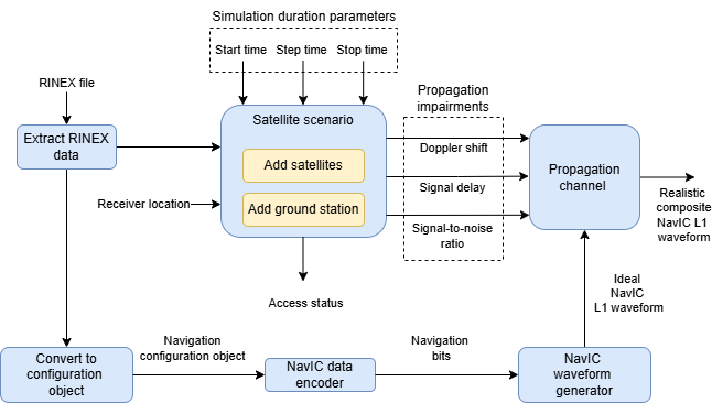
At each step, the NavIC L1 waveform generator produces the interplexed pilot and data signal for all visible satellites. The composite signal passes through the propagation channel, which applies per-satellite Doppler shift, propagation delay, and additive Gaussian noise. The following diagram shows the transmitter end setup.
Receiver end
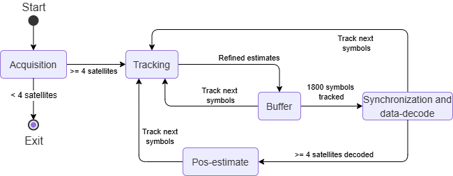
The receiver operates as a state machine. It remains idle for the first rxWaitTime seconds to allow signal to arrive, and then progresses through these states:
Acquisition — Correlates the buffered 20 ms signal against all PRN pilot codes across a grid of Doppler offsets. When a correlation peak exceeds the detection threshold, the satellite is acquired with a coarse frequency offset and code phase.
Tracking — Uses the acquisition estimates to seed two tracking loops per satellite, one for the pilot signal and one for the data signal. Each loop includes a phase-locked loop (PLL) for carrier phase tracking, a frequency-locked loop (FLL) for carrier frequency tracking, and a delay-locked loop (DLL) for code delay tracking.
Buffer — Accumulates tracked symbols from all satellites. The receiver waits until 1800 pilot and data symbols are buffered before attempting the frame synchronization and data-decode.
Synchronization and Data-decode — Searches the pilot symbol stream for the known frame synchronization pattern. After identifying the frame boundary, the receiver extracts 1800 data channel symbols from the synchronized boundary. It then decodes the Bose-Chaudhuri-Hocquenghem (BCH) and LDPC coded navigation message to recover ephemeris and clock parameters.
Pos-estimate — Computes the pseudo-range for each satellite from the measured code delay, determines satellite positions at the transmission time using the decoded ephemeris, and estimates the receiver latitude, longitude, and altitude for the current epoch.
The diagram below illustrates the state machine flow.
% Acquisition requires 20ms of data for NavIC L1
iTxWave = zeros(fs*20e-3,1);

tic
for istep = 1:numSteps
    % Choose the bit index according to the specified start index and step
    % count.
    bitidx = floor((istep - 1)/numCodeBlocksPerBit) + 1;

    % Generate one waveform segment for the current symbol index.
    iwave = navicWaveObj(navData(bitidx,:));

    % Introduce propagation channel effects to the transmitted signal
    gnssChannel.SignalToNoiseRatio = SNRs(:,istep)';
    gnssChannel.SignalDelay = delays(:,istep)';
    gnssChannel.FrequencyOffset = fShift(:,istep)';

    iTxWave = [iTxWave(length(iwave) + 1:end); gnssChannel(iwave)];

    % Optionally write the waveform to a file
    if WriteWaveformToFile ~= 0
        bbWriter(iTxWave(1:length(iwave)))
    end

    if strcmp(nxtState,"exit")
        break;
    end

    % Receiver
    if istep > rxWaitTimeInSteps
        while true
            switch(nxtState)
                case "acquisition"
                    % Satellite acquisition on the pilot channel.
                    [acqd,corrval] = sigAcquisition(iTxWave,1:14);
                    acqIdx = acqd.IsDetected == 1;
                    detectedSatTable = sortrows(acqd(acqIdx,:));
                    PRNIDsToSearch = detectedSatTable.PRNID;
                    numRxSat = numel(PRNIDsToSearch);
                    disp("The detected satellite PRN IDs: " + num2str(PRNIDsToSearch'))

                    if sum(acqIdx) > 3
                        % If four or more satellites are detected
                        for idx = 1:numTrackers
                            sigTracker{idx}.InitialFrequencyOffset = detectedSatTable.FrequencyOffset;
                            sigTracker{idx}.InitialCodePhaseOffset = detectedSatTable.CodePhaseOffset;
                            sigTracker{idx}.PRNID = PRNIDsToSearch;
                        end
                        syncFrame = cell(1,numRxSat);
                        for isat = 1:numRxSat
                            syncFrame{isat} = gnssFrameSynchronizer(SignalType="NavIC-L1",PRNID=PRNIDsToSearch(isat));
                            lastProcessedCntr(isat) = 0;
                        end
                        nxtState = "tracking";

                        if ShowVisualizations ~= 0
                            % Correlation plot for first detected satellite
                            figure
                            mesh(fRange(1):fResolution:fRange(2),0:size(corrval,1)-1,corrval(:,:,1))
                            xlabel("Doppler Offset")
                            ylabel("Code Phase Offset")
                            zlabel("Correlation")
                            title("Correlation Plot for PRN ID: " + PRNIDsToSearch(1));
                        end
                    else
                        % If acquisition fails, that is, less than four
                        % satellites are detected, the receiver machine exits
                        nxtState = "exit";
                        break
                    end

                case "tracking"
                    for idx = 1:numTrackers
                        [trackedWave{idx}(rxistep,:),trackInfo{idx}(rxistep)] = sigTracker{idx}(iTxWave(1:length(iwave)));
                    end
                    nxtState = "buffer";
                case "buffer"
                    % The receiver alternates between tracking and buffering while it accumulates enough samples for synchronization or data decode.
                    for isat = 1:numRxSat
                        sampleCntr(isat) = sampleCntr(isat) + 1;
                        for idx = 1:numTrackers
                            rxSamples{idx,isat}(sampleCntr(isat)) = trackedWave{idx}(rxistep,isat);
                        end
                    end
                    if all((sampleCntr - lastProcessedCntr) >= 1800)
                        nxtState = "synchronization and data-decode";
                    else
                        nxtState = "tracking";
                        break;
                    end
                case "synchronization and data-decode"
                    for isat = 1:numRxSat
                        rxSyms{1} = imag(rxSamples{1,isat}(lastProcessedCntr(isat) + 1:lastProcessedCntr(isat) + 1800).');
                        rxSyms{2} = imag(rxSamples{2,isat}(lastProcessedCntr(isat) + 1:lastProcessedCntr(isat) + 1800).');
                        for k = 1:length(rxSyms{1})
                            alignedFrame = syncFrame{isat}(rxSyms{2}(k), rxSyms{1}(k));
                            if ~isempty(alignedFrame)
                                s = info(syncFrame{isat});
                                syncIdx(isat) = s.SyncIndex;
                                [rxNavConfig,crcError] = HelperNavICDataDecode(alignedFrame,rxNavConfig,"NavIC L1-SPS");
                                lastProcessedCntr(isat) = lastProcessedCntr(isat) + 1800;
                            end
                        end
                    end
                    if height(rxNavConfig.Ephemeris) > 3
                        nxtState = "pos-estimate";
                    else
                        nxtState = "tracking";
                        break;
                    end
                case "pos-estimate"
                    validSatIdx = find(syncIdx(1:numRxSat) > 0);
                    codeOffsetTime = sigTracker{1}.InitialCodePhaseOffset(validSatIdx)/chipRate;
                    trackingOffsetTime = trackInfo{1}(rxistep).DelayEstimate(validSatIdx)/chipRate;
                    frameSyncTime = (mod(syncIdx - 1 + 900,1800) - 900 + 1)*numCodeBlocksPerBit*oneCodeDuration;
                    % Calculate transmission time from these parameters
                    delayEst = codeOffsetTime + frameSyncTime.' - trackingOffsetTime';
                    rho = delayEst*c;
                    eph = sortrows(rxNavConfig.Ephemeris,"PRNID","ascend");
                    A_ref = 42164200;
                    % Convert back to timetable data
                    rxNavDataTT = timetable(eph.TimeStamp, sqrt(eph.delta_A + A_ref), eph.A_dot, eph.delta_n_0*pi, eph.delta_n_dot*pi, ...
                        eph.M_o*pi, eph.e, eph.AOP*pi, eph.i_0*pi, eph.IDOT*pi, eph.C_is, ...
                        eph.C_ic, eph.C_rs, eph.C_rc, eph.C_us, eph.C_uc, eph.RateOfRAAN*pi, eph.omega_o*pi);
                    rxNavDataTT.Properties.VariableNames = ["sqrtA" "A_DOT" "Delta_n0" "Delta_n0_dot" ...
                        "M0" "Eccentricity" "omega" "i0" "IDOT" "Cis" ...
                        "Cic" "Crs" "Crc" "Cus" "Cuc" "OMEGA_DOT" "OMEGA0"];
                    satpos = HelperNavICSatelliteStates(HelperGNSSConvertTime(max(eph.WN) + 1024, max(eph.ITOW)*7200 + max(eph.TOI)*18), rxNavDataTT);

                    [rxposest,~,hdop,vdop] = receiverposition(rho,satpos);

                    estRxPosNED = lla2ned(rxposest,rxPos,"ellipsoid");
                    distanceError = vecnorm(estRxPosNED);
                    fprintf("Estimated receiver position is [%.4f° %.4f° %.0f m] with an estimated error of %.2f m.\n", rxposest(1),rxposest(2),rxposest(3),distanceError);

                    if hdop > 20
                        warning("Dilution of Precision (DOP) ratings are poor. The position " + ...
                            "estimation error can be high.")
                    end
                    nxtState = "tracking";
                    break;
            end
        end
        rxistep = rxistep + 1;
    end
    if ~mod(istep,1/stepTime)
        disp("Processed " + (istep*stepTime) + " sec of data at the receiver.")
    end
end
The detected satellite PRN IDs: 2 6 9 10
Processed 1 sec of data at the receiver.
Processed 2 sec of data at the receiver.
toc
Elapsed time is 45.919279 seconds.
If simulationDuration is too short for a full data decode, load reference data for the default example configuration to demonstrate the final positioning step.
if rxistep <= minStepsForPosEst
    % Load reference parameters for the default example configuration.
    load NavICL1ReceiverPositionProperties;

    defaultRINEXFileName = "IITK00IND_R_20243400400_01H_MN.rnx";
    defaultRxPos = [17.361786 78.474774 25];

    if ~(strcmp(rinexFileName,defaultRINEXFileName) && isequal(rxPos,defaultRxPos))
        warning("Estimated receiver position may be different from what you provided" + ...
            " as the simulation did not run for entire data." + ...
            " To get accurate receiver position, run the example" + ...
            " for at least 37 seconds of navigation data.");
    end

    [rxposest,~,hdop,vdop] = receiverposition(rho,satpos);
    estRxPosNED = lla2ned(rxposest,rxPos,"ellipsoid");
    distanceError = vecnorm(estRxPosNED);
    fprintf("Estimated receiver position is [%.4f° %.4f° %.0f m] with an estimated error of %.2f m.\n", rxposest(1),rxposest(2),rxposest(3),distanceError);
end
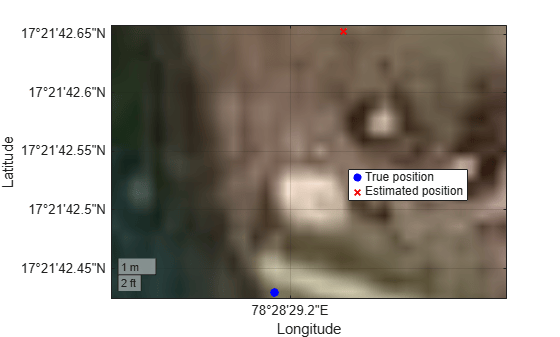
Estimated receiver position is [17.3618° 78.4748° 15 m] with an estimated error of 12.02 m.
If you enable visualizations, display the most recent tracked samples at the output of the tracking stage.
rxistep = rxistep - 1;
if ShowVisualizations ~= 0
    % Show the last 1000 tracked samples from the data-channel tracker output.
    rxconstellation = comm.ConstellationDiagram(1,ShowReferenceConstellation=false, ...
        Title="Constellation diagram of signal at the output of tracking");
    rxconstellation(trackedWave{2}(max(1,rxistep - 999):rxistep,1)/rms(trackedWave{2}(max(1,rxistep - 999):rxistep,1)))
end
If you enable waveform logging, release the baseband file writer after the simulation completes.
if WriteWaveformToFile ~= 0
    % Release the waveform writer object
    release(bbWriter)
end
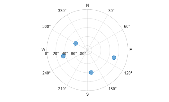
When position estimates are available, plot a sky plot and compare the true receiver position with the estimated position on geographic axes.
if exist("rxposest","var")
    [az,el] = lookangles(rxposest,satpos);
    figure
    skyplot(az,el)

    figure
    gx = geoaxes;
    hold(gx,"on")

    geoscatter(gx,rxPos(1),rxPos(2),40,"b","filled",DisplayName="True position")
    geoscatter(gx,rxposest(1),rxposest(2),40,"xr",LineWidth=1.5,DisplayName="Estimated position")

    legend(gx,Location="best")
    geobasemap(gx,"satellite")
end
Further Exploration
Change the receiver location, sampling frequency, or simulation duration to see how each setting affects the final position estimate. You can also try a different RINEX file with more visible satellites.
Local Function
function outputTable = processRinexData(data,info)
%PROCESSRINEXDATA Extract required navigation parameters from RINEX data.

fileVersion = round(info.FileVersion);

% Define required columns
requiredCols = ["Time", "SatelliteID", "SVClockBias", "SVClockDrift", ...
    "SVClockDriftRate", "Cis", "Cic", "Crs", "Crc", "Cus", "Cuc", "M0", ...
    "Eccentricity", "omega", "OMEGA_DOT", "OMEGA0", "i0", "IDOT", ...
    "A_DOT", "Delta_n0_dot", "Delta_n0", "sqrtA"];

if fileVersion == 3
    originalTable = timetable2table(data.NavIC);
    existingCols = intersect(requiredCols,originalTable.Properties.VariableNames,"stable");
    missingCols = setdiff(requiredCols,existingCols,"stable");
    outputTable = originalTable(:,existingCols);
    if ~isempty(missingCols)
        outputTable = [outputTable, array2table(zeros(height(outputTable),numel(missingCols)), ...
            VariableNames=missingCols)];
    end
    % Delta_n0 and Delta_n0_dot are not available in RINEX 3.xx.
    % Set Delta_n0 equal to Delta_n and assume Delta_n0_dot is zero.
    if ismember("Delta_n",originalTable.Properties.VariableNames)
        outputTable.Delta_n0 = originalTable.Delta_n;
    end
elseif fileVersion == 4
    originalTable = timetable2table(data.NavIC.L1NV.EPH);
    outputTable = originalTable(:,requiredCols);
end
end
Supporting Files
This example uses these supporting files.
HelperAddNavICSatellite.m— Add NavIC satellites to the satellite scenario objectHelperGNSSConvertTime.m— Convert GNSS week number and time of week to datetime and backHelperGNSSChannel.m— Provide a GNSS propagation channel with Doppler shift, signal delay, and random noiseHelperGNSSSignalAcquirer.m— Acquire visible NavIC pilot-channel signalsHelperGNSSSignalTracker.m— Track NavIC pilot and data channelsHelperNavICConfig.m— Create a configuration object for NavIC navigation dataHelperNavICDataDecode.m— Decode NavIC data bitsHelperNavICDataEncode.m— Encode navigation data bits from the configuration objectHelperNavICRINEX2Config.m— Update NavIC configuration object parameter values using RINEX file dataHelperNavICSatelliteStates.m— Compute satellite states for receiver position estimation
References
[1] Indian Space Research Organisation (ISRO). "NavIC Signal in Space ICD for Standard Positioning Service in L1 Band." Version 1.0, SAC/ISRO, Ahmedabad: 2023.
See Also
Functions
gnssBitSynchronize|gnssFrameSynchronizer|navicL1Codes|gnssCACode|ionosphericOffset|cemicmod

